Building The Garden Of Eden Pinball Machine
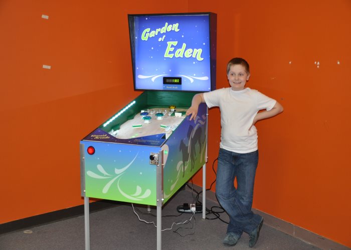
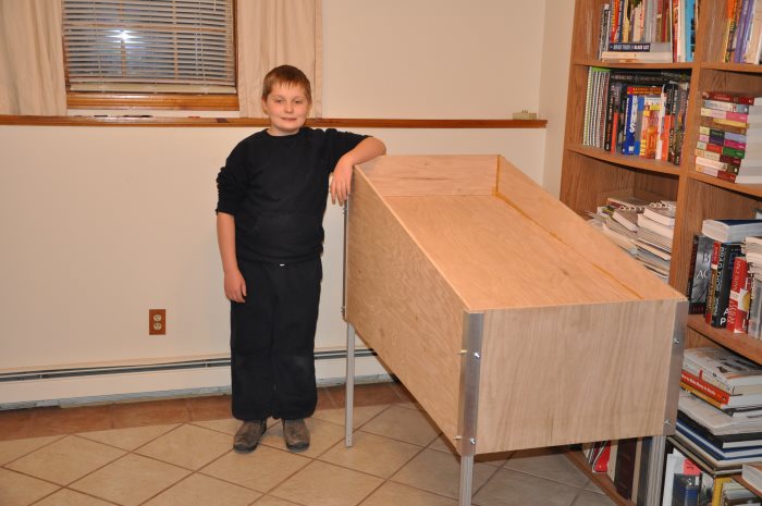
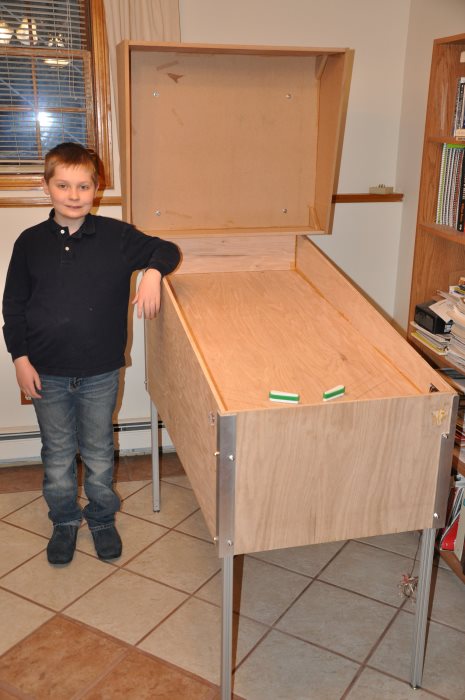
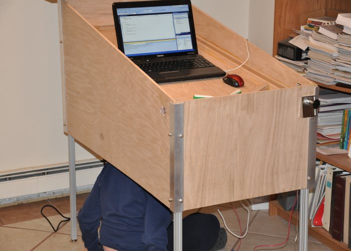
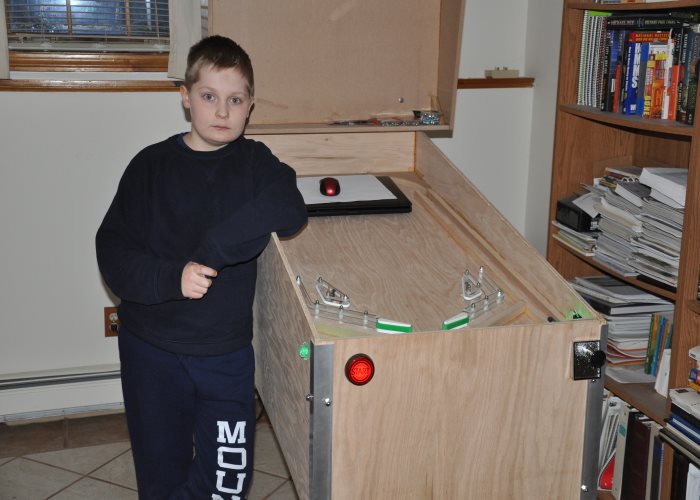
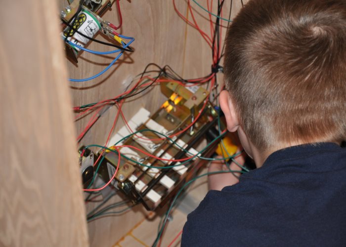
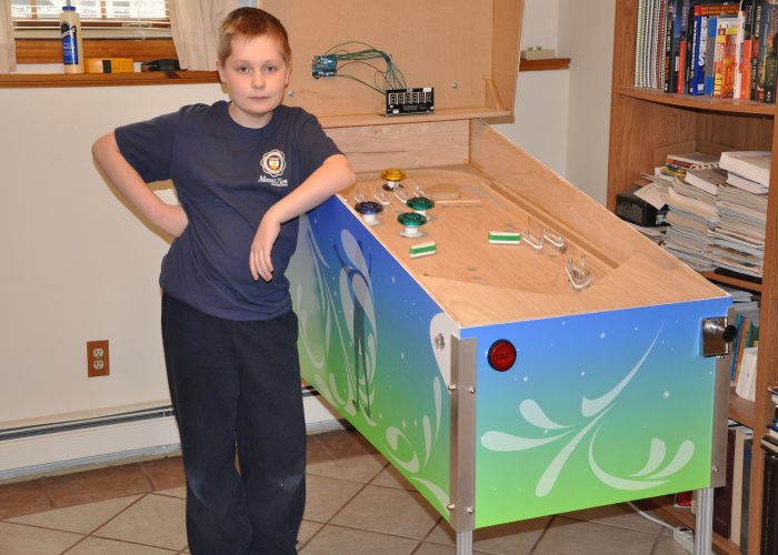
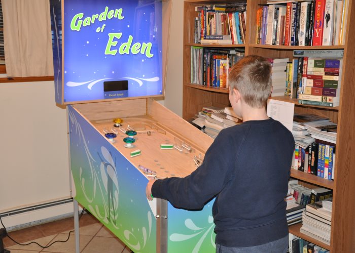
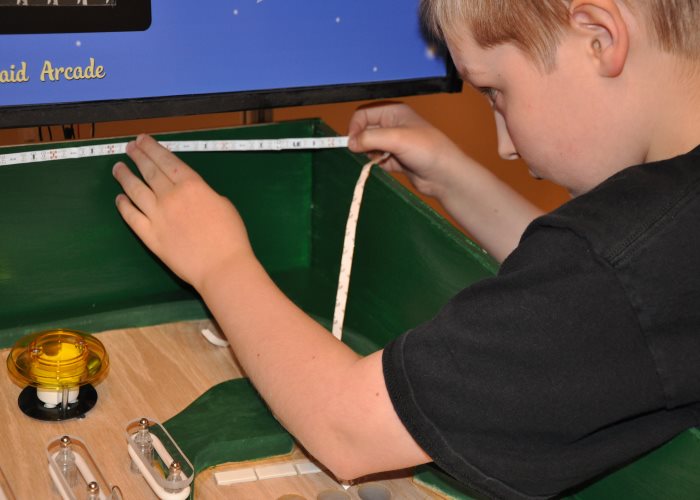
That is the 11-year-old me around 2-3 weeks before the school exposition. Sadly, the pinball machine does not work anymore. There are several loose wires between the Arduinos and I have no idea where they go.
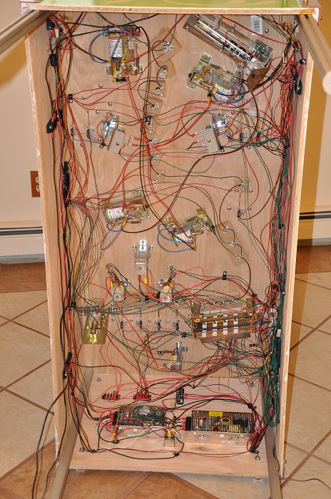
The 11-year-old me wired and designed all of that. Over 500 feet of wire.
This page is a redo of the page that has been on the internet from 2014-2018.
For those of you who had seen this when I was younger, I have added in more technical descriptions of what is going on, my ideas at the time, to the best of my memory, and numerous spelling corrections.
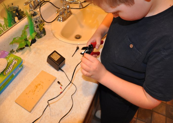
This page has also been restyled, and has had many changes made. The original publication was in 2014. This was before I had my own workroom. I did all the hacking/soldering in the downstairs bathroom.
If you want to view the old, unmodified, page, it is here. Beware: There are many dead links, as it is just a standalone page.
I learned how to solder to do this project. My soldering skills didn't drastically improve until I built the LED cube. Unfortunately, due to the amount of unsoldered wires in the machine, the machine did not last long after my school's exposition. I have since tried many times to get it up and running again. I'm not sure if all the arduinos were somehow erased.
On the bright side, there are plans to scrap the old one, and build two machines in its place. My Dad will build one, I will build one. We will have a third party play them, without knowing who did which machine. The best machine wins. I plan on winning with more than 50 multi-ball modes.
The machines will be built whithout us helping each other. My Dad may not have many bells or whistles in his electronics, but he could design some driver boards. My dad is an awesome artist, and he can design artwork better than anybody I know. There is no doubt he will trounce me in the art department.
I, on the other hand, could easily design kick-butt boards, with all the bells and whistles, but I will be super lucky if I can achieve artwork better than a 1960's EM. That alone could make me lose the competition. I will have to focus on depth to my gameplay. This will be a tough competition.
I am not exaggerating when I say that basically everything I learned about electronics at that time came from this project. Some things I learned included:
- How to solder
- How to remember what large amounts of wires do without a schematic.
- How use an Arduino better
- I didn't realize it at the time, but the loop counter.
- How to keep multiple power supplies working.
- Why we have a common ground across all power supplies.
- Why we don't have one resistor pulling down 20 signals. It just bridges them all...
- Why we don't use a 7805 to drive about 6 amps of items...
- Why I avoid copperless perfboard like the plague.
- I didn't realize it at the time, but why it is important to have enough amps of current supplied.
This project basically gobsmacked everyone. Since I showed it off at the exposition as an 11-year old, I have never seen so many adults absolutely speechless about what anyone has done. There was not one adult whose jaw did not drop that night.
And, quite arguably, nothing I have done has come close since. I am going to make one last push to top it. For my big school project this year, I will attempt to build a 5 - 6 foot tall humanoid robot.
As it stands right now, the pinball machine is not finished, and never will be. It lacks playfield art, and the "Walk with God" ramp. We just couldn't figure out how to do acryllic cutting to make the ramp in time.
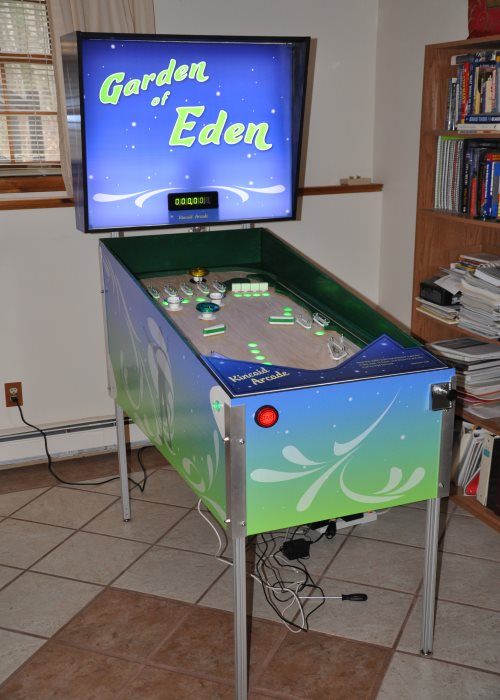
Garden of Eden pinball
My machine's theme was The Garden of Eden. (Inside joke. My school calls it the "Eden Exposition", because our God is a Creator, and therefore we need to make things, too. That's how we came to the Garden of Eden theme.)
The original project deadline was May 8th, 2015.
What I did:
- Designed the game in a pinball simulation program called Future Pinball
- All of the wiring. There was one time that my Dad could've made a 5 minute change in the code
because some of the lights were going out of order. I offered instead to switch some wires.
My parents told me I came up about 3 hours later, with the light sequences correct. - About half of the soldering.
- Created the gameplay rules.
- Convinced my Dad that we needed to use EOS switches instead of the driver board for the flipper coils.
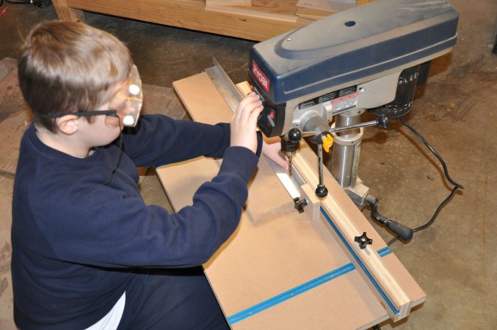
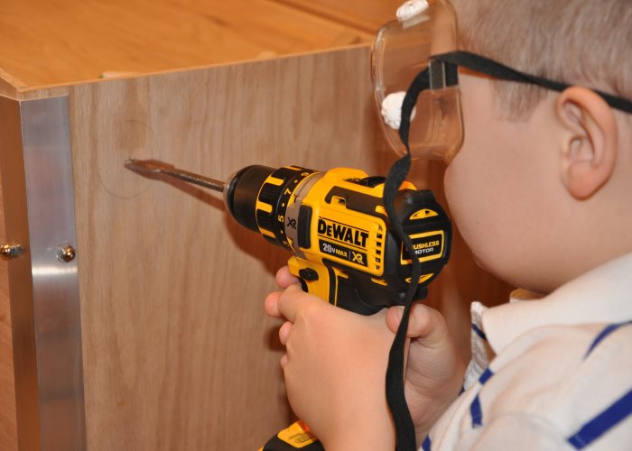
- Almost all the playfield drilling. (My dad had to make a jig for drilling the lighted inserts.)
What my Dad did:
- The graphics
- Almost all of the code (I did 1 or 2 light sequences)
- About half of the soldering.
- All the plexiglass cutting, including the inserts & their holes.
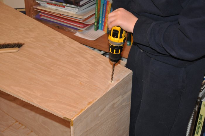
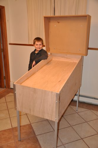
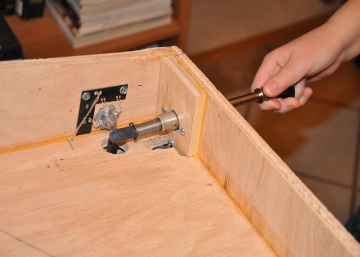
These metal pieces go on the outside of the cabinet. They hold the legs in place. We used aluminum extrusions, that my Dad had bought for a CNC machine, if I remember correctly. (We had already built the basic cabinet, the playfield is 2 feet by 4 feet.)
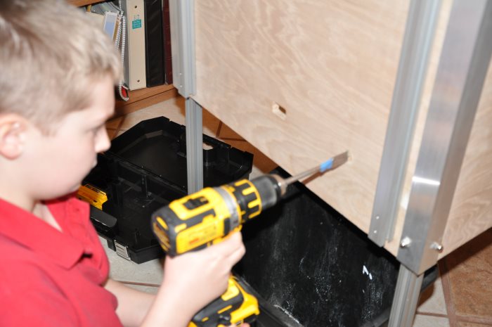
The next step is to mark where those holes line up on the cabinet and drill them. Bolts slide through, and then the extrusions will slide in after that. It makes inserting and removing the legs very difficult.
After finishing up the cabinet, there was about 2 months of inactivity on the project. Then things really started to become real.
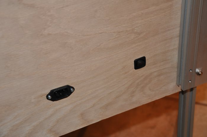
We were walking through the local surplus store, and saw some metal power plug inserts. We thought: "Why not?"
'Kinda funny when I think how the machine has a total of 5 plugs & wall - warts hanging out of it for operation. We weren't ready to have me work with wall current just yet.
And when they were mounted in:
These are all the flipper mechs we got. Due to inadequate packaging, the edges of the coils were broken off, and we had to get replacements. That delayed us by quite a bit. Pinballlife actually came up with a new way to package their coils after emailing back-and-forth to do a return and replacement.
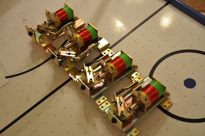
After that whole fiasco, we got the flippers mounted in. We looked at the manuals and apron areas for other games to help figure out the return lanes. You can see Black Knight and The Adams Family manual printouts on the playfield.
I put in the buttons and switches. We were using the driver board to handle the coils. We couldn't figure out why it wouldn't work. My best guesss is a lack pulldown resistors.
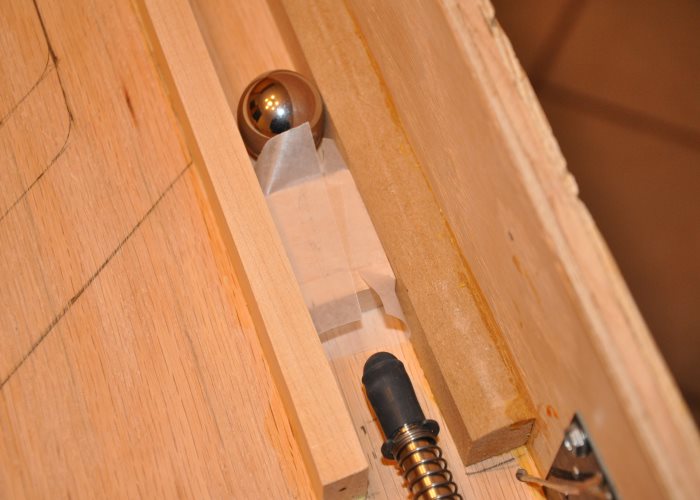
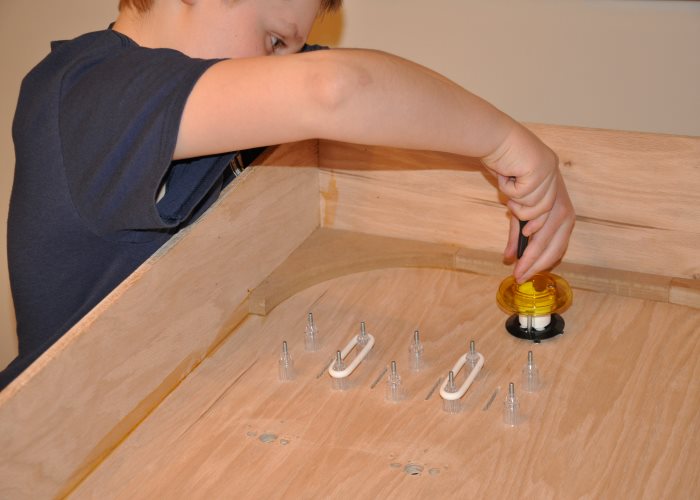
The plunger took forever to figure out. It has a wierd shape on the back. This was the cost of using a modern metal plunger instead of an EM-style plunger.
It also had this annoying tendency to hit the leaf switch for the flipper button.
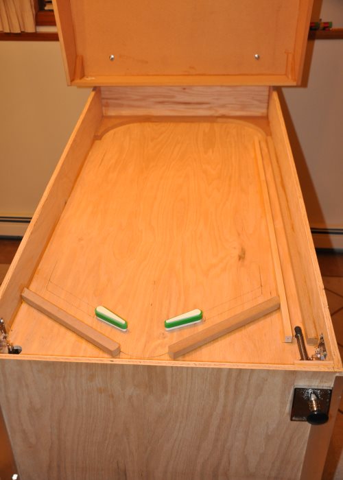
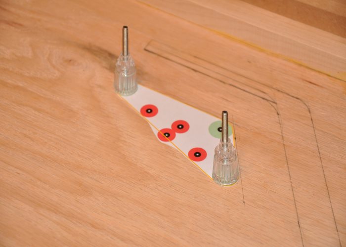
Start with the simple things. It helps you stick with the project. The launchlane retaining walls were good things to work on.
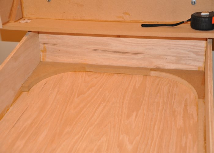
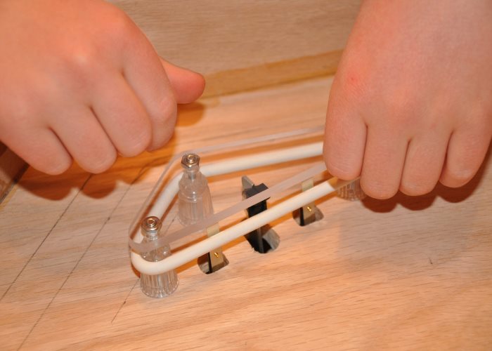
Some of my Dad's favorite phrases are "Silly gets us hurt," and "Always make a jig." We made two blocks of wood to serve as spacers for gluing in the ball launch lane. They did their job well -- they were just large enough for the ball to roll through.
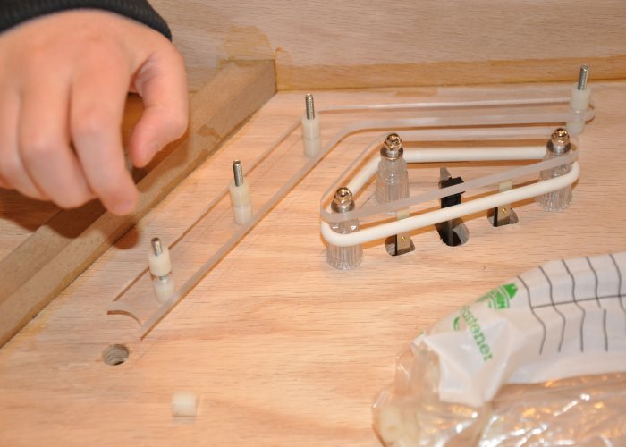
Here we can be seen gluing in the outlanes. Just pieces of particle board. The apron would later fit perfectly over the top.
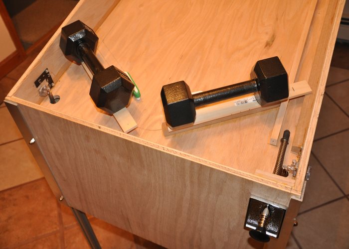
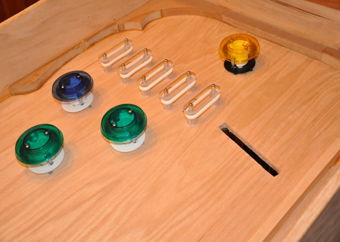
Without the weights. Still a long way to go.
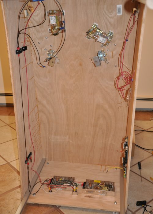
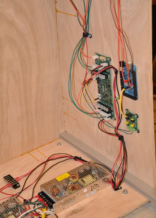
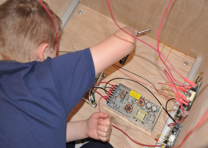
From left to right: 5 volt supply, and 36 volt supply.

Looks pretty, but I need it to do stuff.
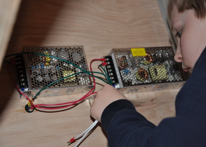
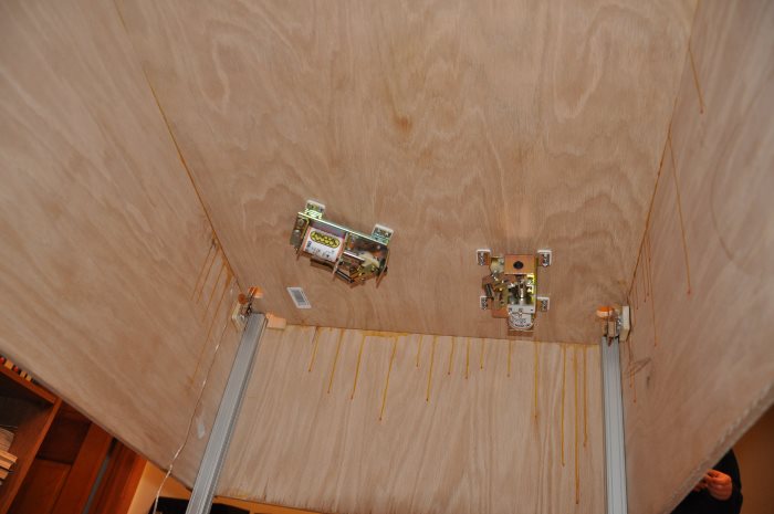
You would not believe the amount of ground points needed on this machine. There were many more of these added as time went on.
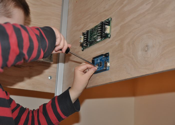
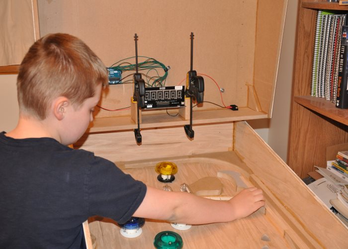
To make it do things, I added in a Arduino Mega 2560, a rs-485, and a Power Driver 16 board. There are three Arduinos: two Megas and an Uno. One for lights, one for game control, and the Uno for the score.
One of the arguments I'd get into with my Dad with was whether or not Arduino or Visual studio was better. I lost. Looking back, I find that hilarious.
There wasn't much progress made for the next few months as we were just trying to figure out why the code wasn't controlling the flippers properly. The issue was an imperfect implementation of loop counters, and delays that were too large locking up the program. The Arduino can't read switches while executing a delay(). This is why I wrote my Golden Spike program the way I did.
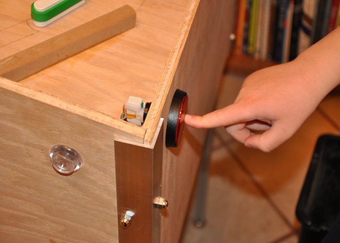
The game was always going to be set to free play, so we just needed a start button. I wanted us to use coin mechanisms, but my Dad wasn't willing to pay for an unnecesary feature. Now that I am grown up, and have to make that choice all the time, I agree.
I remember seeing that Data East start button for sale on Marco Specialties. I just had to have it.
Here it is mounted in.
Like my Dad always said: "Make a template!" So that's what we always did...
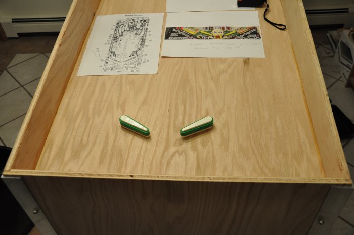
We never got to apply graphics to the slingshots. We only ever put graphics on the side of the cabinet.
My Dad used his new bandsaw to make the plexiglass. We also ended up making several trips to Ace Hardware to get the nylon spacers.
Wiring up the slingshots. Heh. Left the barcode on the bottom of the playfield.
Controlling the flippers with the Arduino would work about half the time. But we were making progress. I was really starting to get excited.
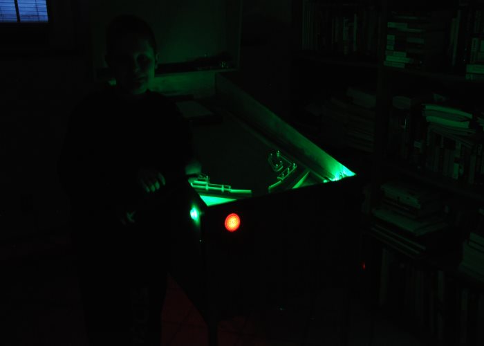
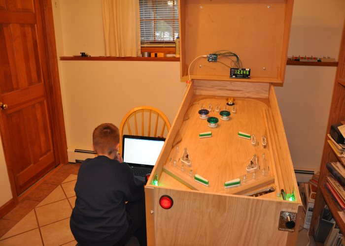
A night shot of the machine!
We only ever got around to doing the other stuff, like adding the pop bumpers and the "E-D-E-N" rollovers because I finally convinced my Dad that we weren't getting anywhere with trying to code the flippers, and it wouldn't be too difficult for me to change the coils and wire up the E.O.S. switches to make it work. My Dad finally agreed, and it worked the first time. It was very exciting.
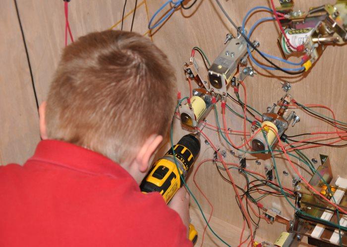
Some of the additional wiring I had to do. I don't remember why I had an LED in pin 13...
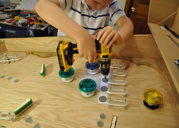
Here I am adding the Pop Bumpers. Oh boy. It was a fun and tedious process. We went through some iterations with scrap wood to figure out the holes that needed to be drilled for them.
The pop bumper I am adding here was the bumper in the land of Havilah, where there was good Gold.
Big points awarded of you managed to hit it. Kinda but not very difficult.
The number of wires here was about to go up exponentially.
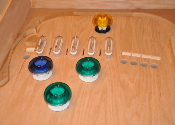
Here I am, adding the other pop bumpers. The blue one is the river Pishon, the green ones were just trees.
We only put two rubber bands in the "E-D-E-N" area, because we had not ordered enough. We just bought a kit to re-rubber a pinball machine. I think it was for Star Trek: The Next Generation.
The playfield was really coming along. You can just make out the cutout for the ball trough. It is a reproduction ball trough from Star Trek: The Next Generation. The Slingshots were also from Star Trek: The Next Generation, too.
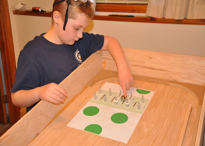
I am now working on adding the "Name The Animals" bank of 4 drop targets.
It took forever to add these drop targets. They also sometimes wouldn't reset properly. I think the coil wasn't strong enough.
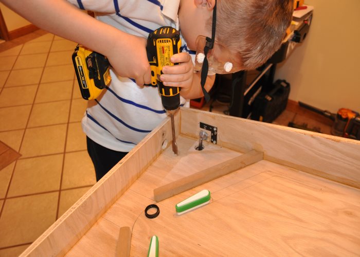
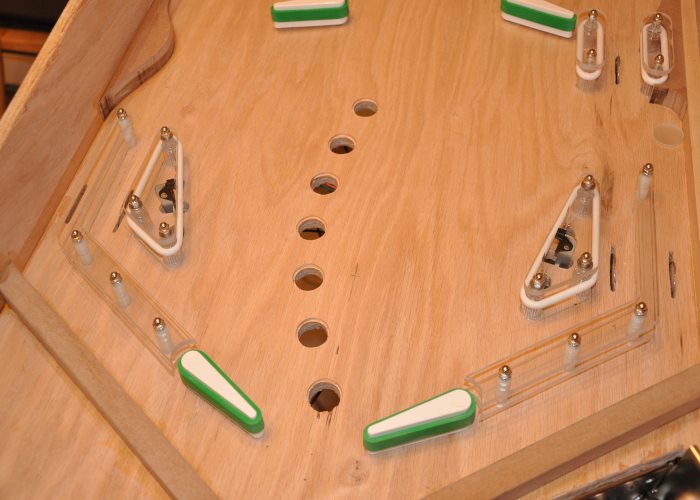
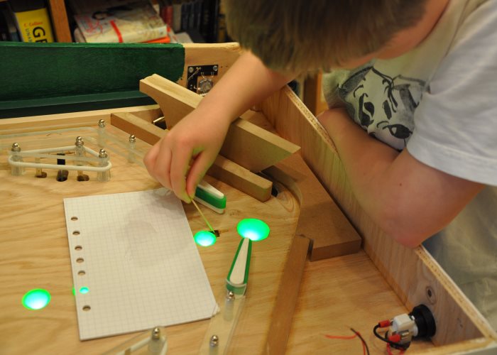
Adding all those rollover switches took forever. I made so many holes, and had to reposition them many times. They also rubbed up against the sides of their holes, and that made me need to reposition them again. I was working with a gap an 1/8th inch wide. I eventually got them all, though.
Here I am, adding some more hardware to the playfield.
You can just barely see the "Creation of Eve" drop target. I think you could only hit that one once per game.
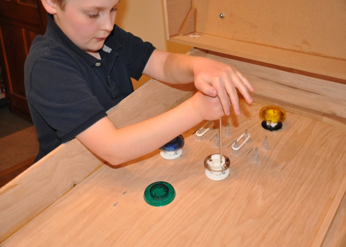
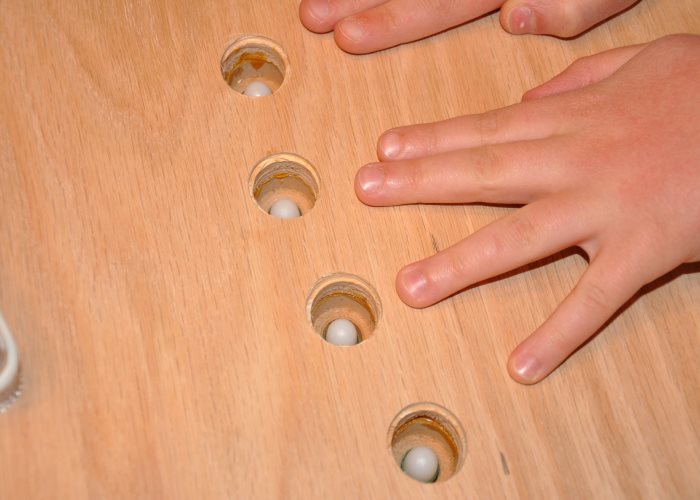
Adding the lighted inserts was a difficult task. It took forever. We bought a whole bunch of green lights from Marco Specialties, and they looked rather nice.
The "end-of-ball bonus" lights. I think the highest bonus you could get was 7,000.
We discovered a void in the wood on drilling the lowest insert down. We had to fill it in with Epoxy.
I am drilling pilot holes to facilitate the drilling of the holes for the "E-D-E-N" inserts.
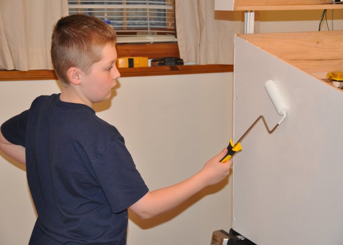
I'm priming the cabinet a solid white. It helps the graphics look good.
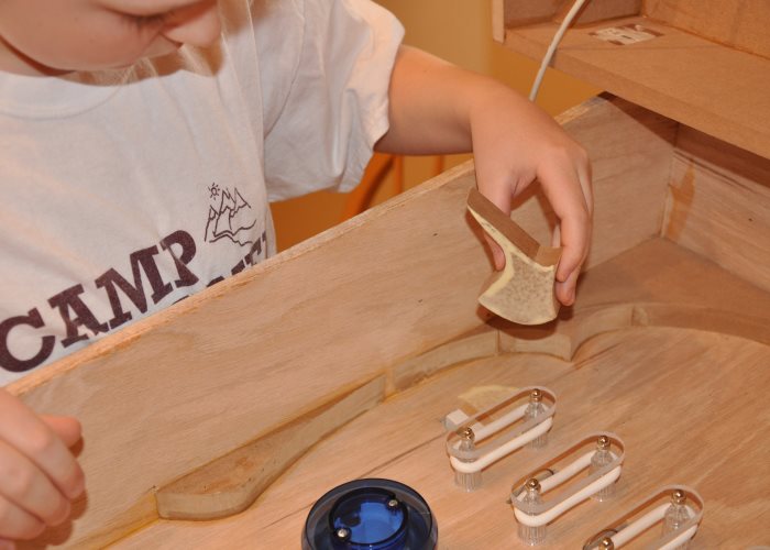
Applying the graphics was difficult. I am using a paper towel to help evenly distibute force without having my hands get stuck on it. It also helped get rid of any bubbles.
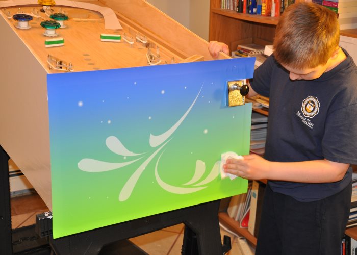
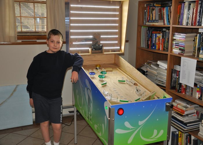
We finished putting on the graphics for the body of the cabinet. We still needed to put the graphics on the marquee and apron.
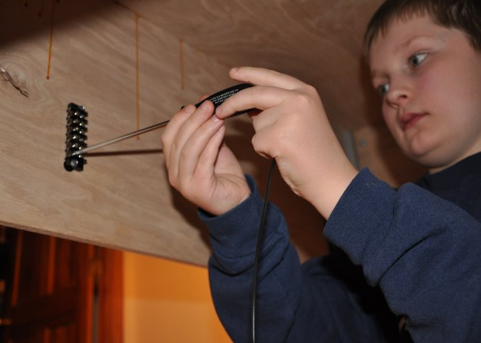
I was hacking a 9 volt wall-wart. I believe it was a 850 milliamp one. I think it was used to power the arduino in the Marquee that controlled the Pinscore dislpay.
I was adding the last of the playfield pieces. They were bandsawed by my Dad.
I left the gap between those two pieces because I wanted another place for the ball to go to get the Gold bumper.
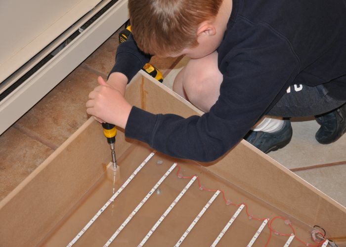
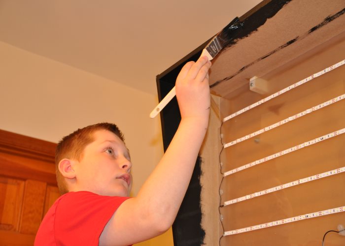
We used LED striplighting to make the backlight for the Marquee. It was one of my first solder jobs. I think it looked really good.
It works! First try!
Its not too useful out of the cabinet...
That. Looks. AWESOME!
I just need to do a little painting and a few other small things.
We used some frosted lamps that would emit green when lit.
Another skill I learned: Painting.
There was a big void in the plywood that we discovered. We had to fill it in with Epoxy.
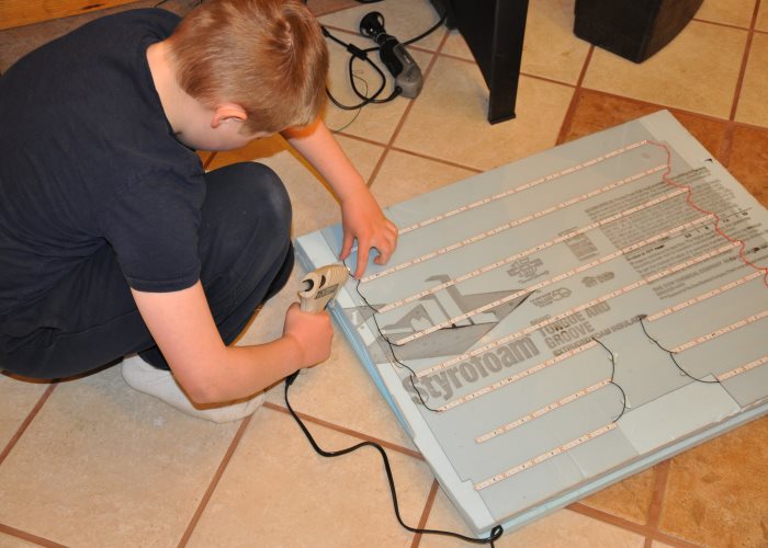
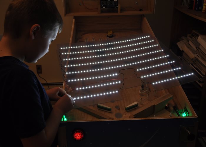
I added LED striplighting to help illuminate the playfield. It was way too bright. We ended up switching to a different set of striplighting.
So much hard work. So much stimulation to the economy. So many hours lost for this project. So many burns from using a soldwring iron. Also: Cleaning up is not usually my specialty. You can see the screwdriver on the floor.
We had to bring the machine to school a week before the exposition. We had to use a U-Haul to bring it to school. I was excited as all-get-out.
The exposition was on May 8th, 2015.
Also: The wispy stuff is the "Breath Of God." Everything living has had the breath of God breathed into them.
All in all, I'm glad I didn't play Civilization IV or Homeworld 1 as much as I could've. My Dad had to literally tear me away from my computer on some days.
We don't have that problem anymore, as I would rather work on a project most of the time.
This iteration of the page was written sometime over Summer Break of 2018.
This page was last updated 1/5/2022
Spelling, grammar, and readability corrections.