The Pocket Encouragement Device
Biblical encouragement at the press of a button!
This is another one of my lengthy write-ups. Clicking any of the links below will take you to that point in the write-up.
- Background and How I Came up with the Pocket Encouragement Device (The Idea)
- Design of the "A" Revision
- Design of the "B" Revision
- Operation
- How I Assemble them
- Mounting it into the case
Some videos of them in operation:
UPDATE 8/30/2020: I have added the design files to the Downloads page for anyone who is interested.
The Idea
The Pocket Encouragement Device was an idea that popped into my head while I was laying awake at night during workcampNE. (It is basically the New England version of Habitat for Humanity. Check it out!) I thought about designing a little keychain-sized device that provided biblical encouragement at the press of a button. My original idea consisted of X3 alphanumeric displays and a minimal arduino on a custom circuit board. The device would display each verse three letters at a time, and would display a new verse each time the button was pressed.
Unfortunately, the school year was coming to a close and I didn't have much time to work on it. I began the design work with around three weeks left before break. Since this project was pretty much entirely an electronic design, I began with drawing up a minimal arduino in EAGLE and going from there.
It didn't take long for me to realize that reading something three letters at a time wouldn't work very well, so I switched to an LCD. The breadboard prototype looked like this:
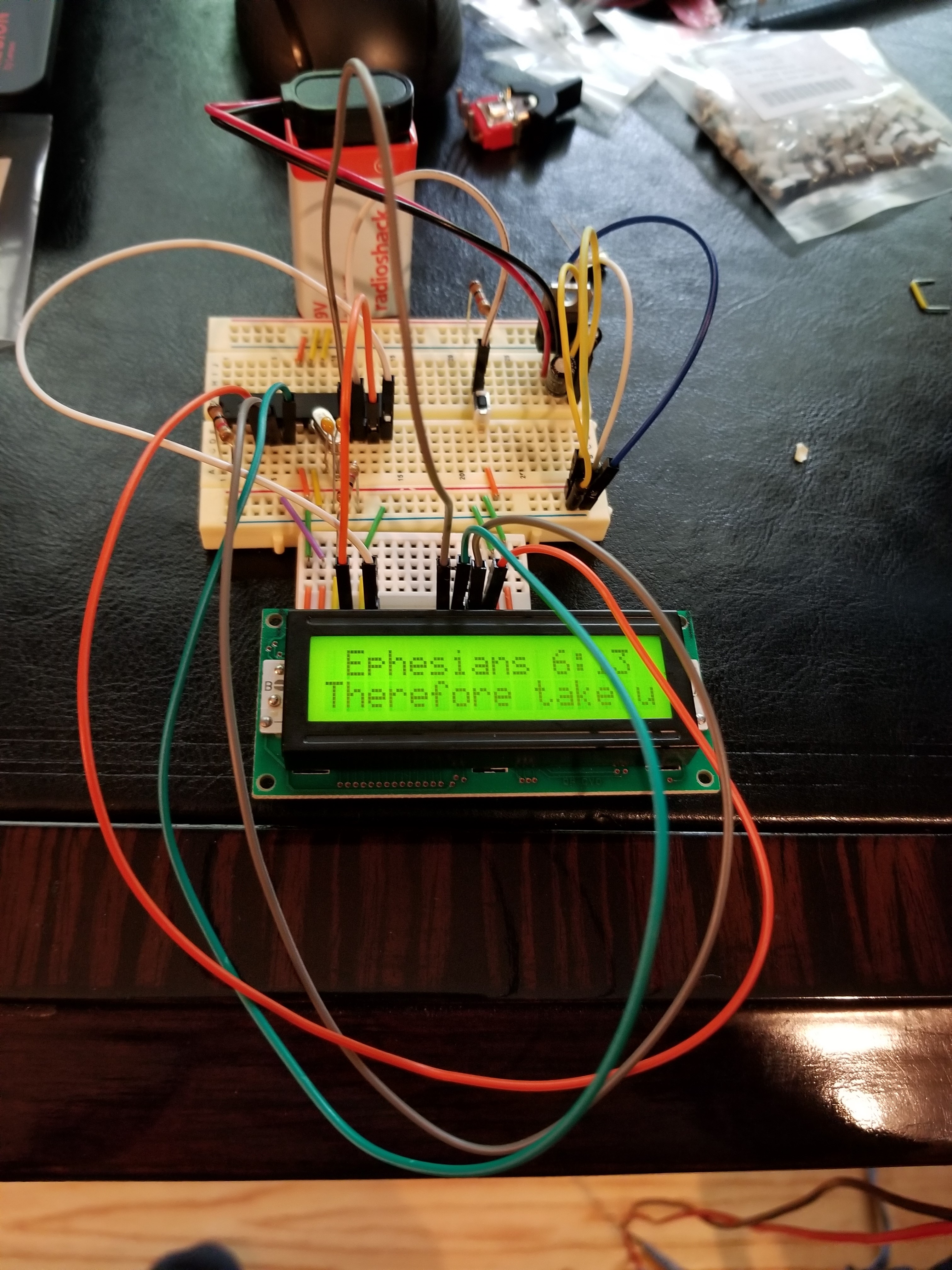
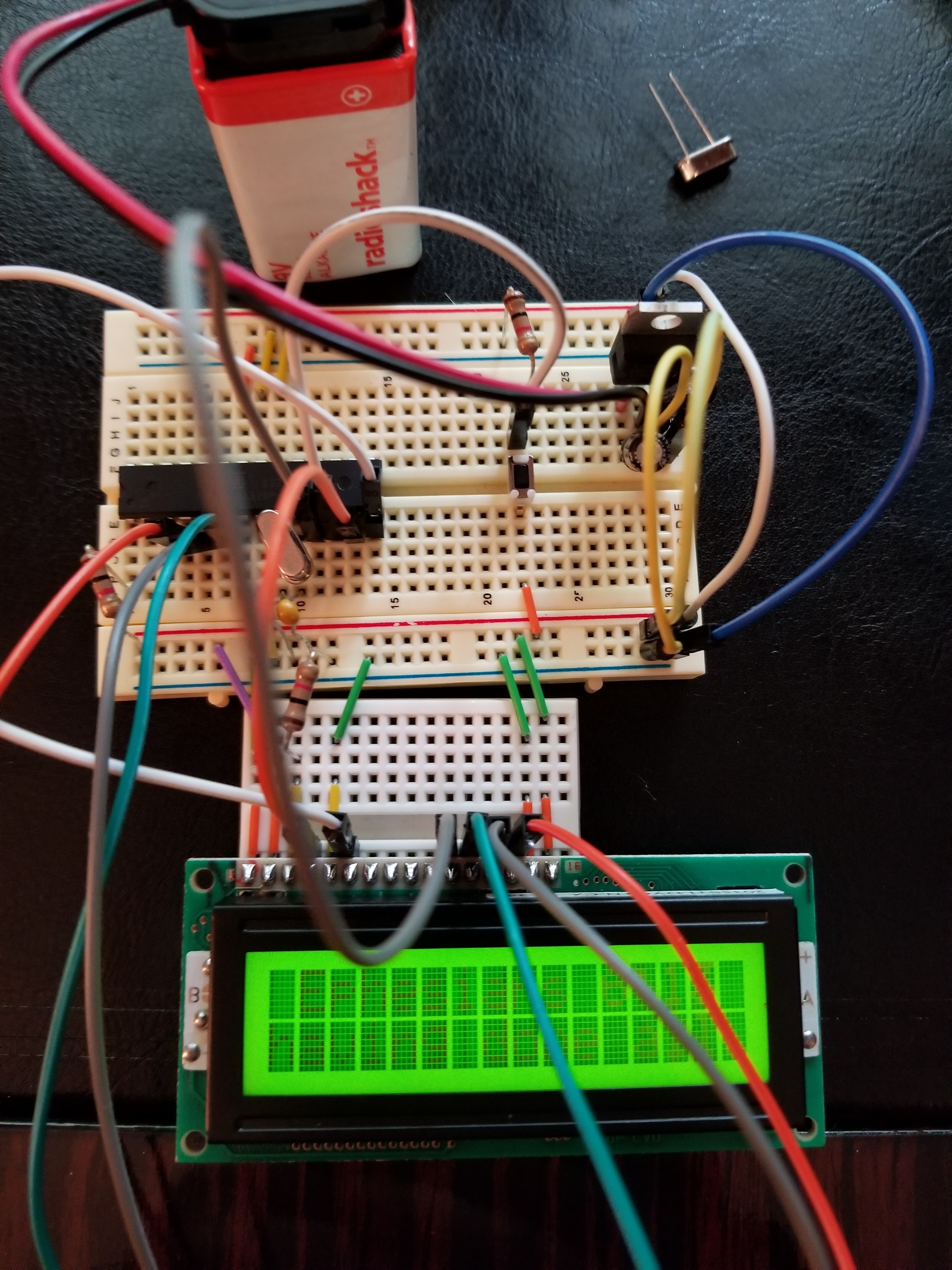
The 'proof of concept' device, running very buggy code.
As you can probably see, I was learning about standard deviation in math class that week. :)
Designing the "A" Revision
Later, I designed up a 'REVISION-A' prototype board, and I had QuickTurnPCB (in South Korea) fabricate it. (All 30 of them. A choice I would later regret.) Apparently, they ran out of HASL material, becuase they upgraded me to ENIG for free. Again, I was very pleased with the boards:
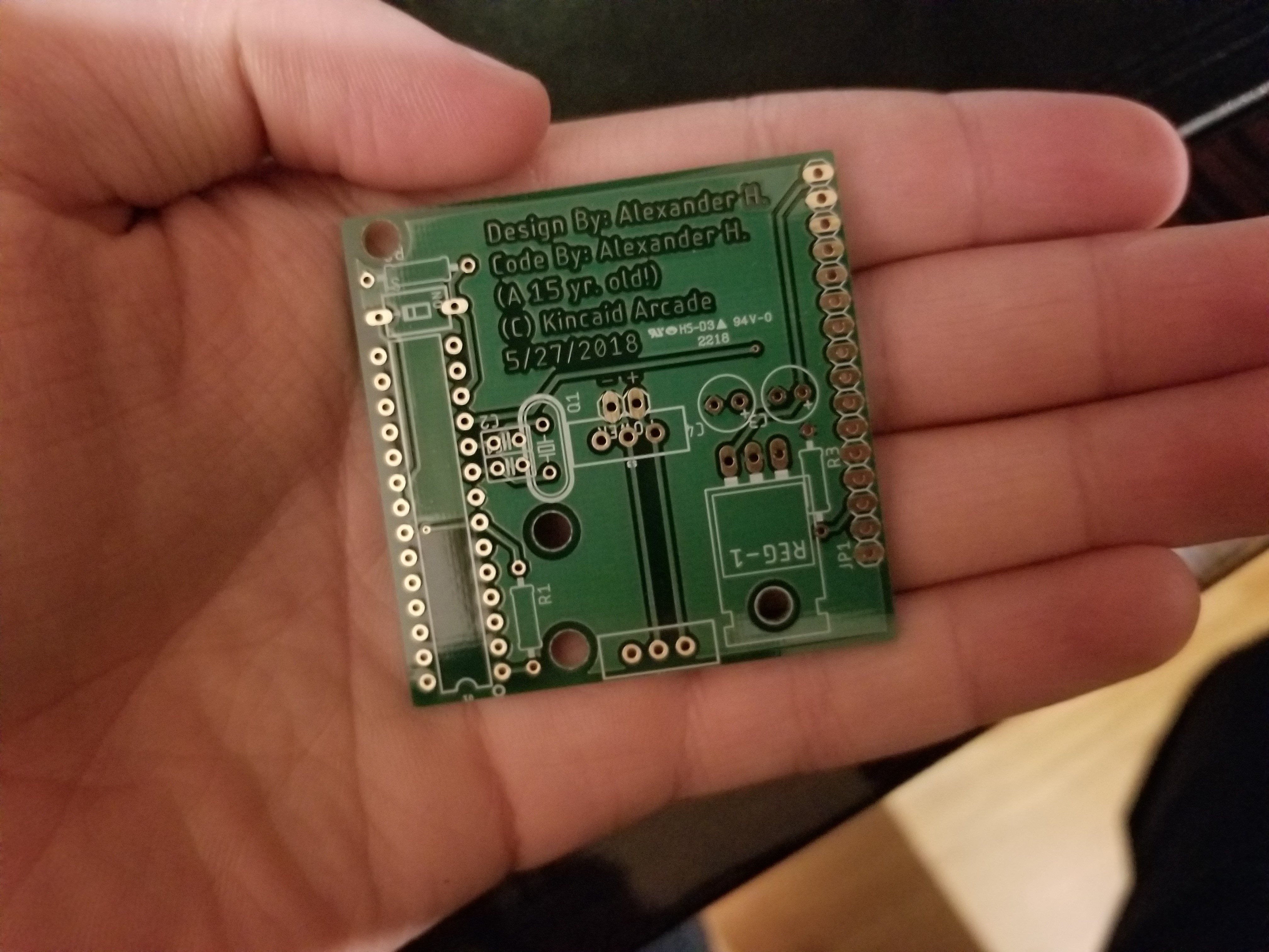
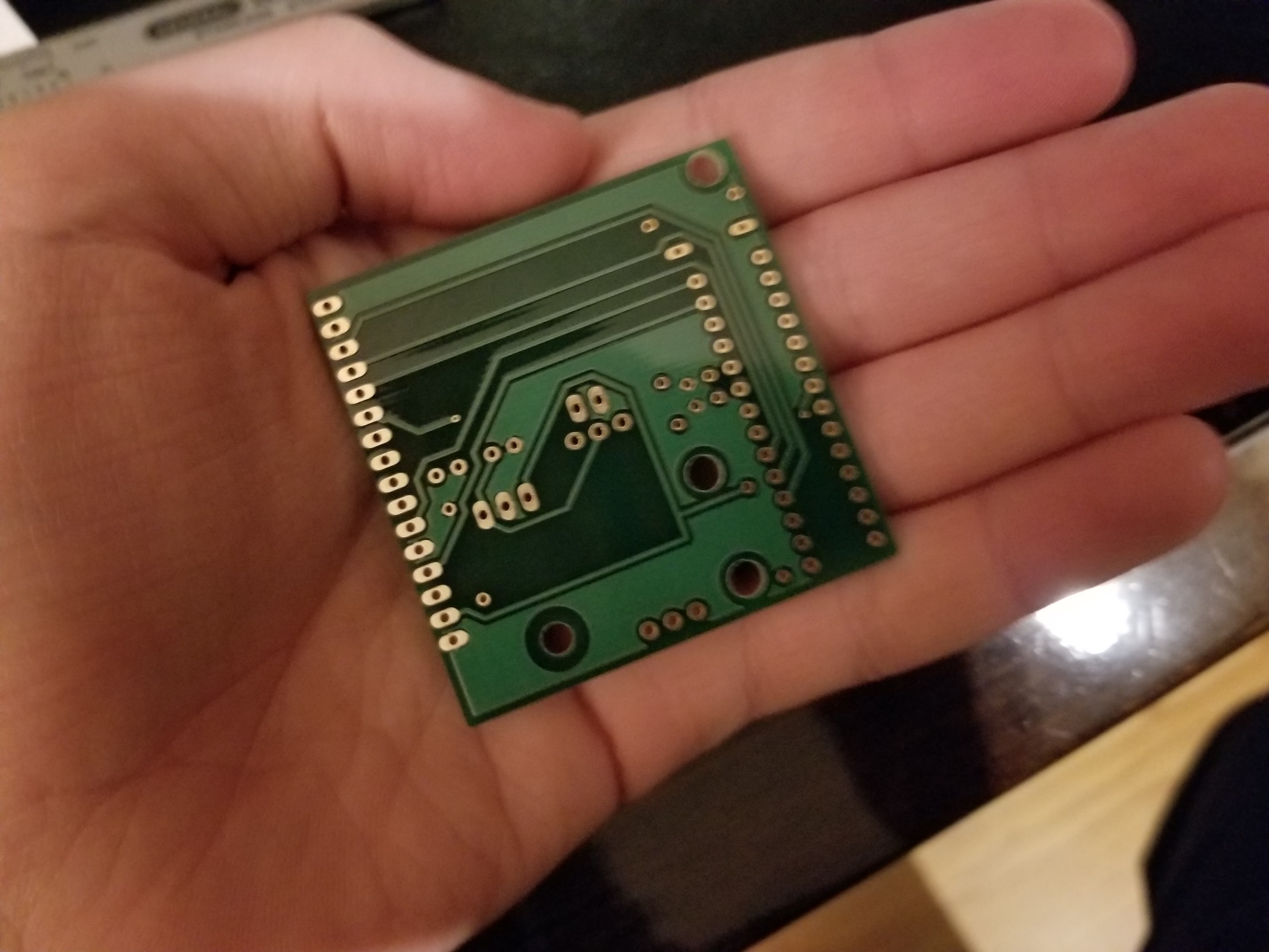
A REVISION-A Pocket Encouragement Device PCB.
The next step was to make cases. I printed 3 more prototype cases before I realized that the REVISION-A Pocket Encouragement Device was *just* a little larger than I had imagined.
Prototype Cases
Numbers 1-4 were never finished. Number 1 was the only one that got a partial case.
The pictures up above pretty adequately describe why I stopped with the REVISION-A pretty early on. The thing was ginormous; about the size of my hand! It probably would've been 3 inches deep if I finished the case. Unfortunately, that left me with about 26 circuit boards that I'd never use. Souvenirs, maybe?
Designing the "B" Revision
So, I started work on the REVISION-B circuit board. I designed it with size in mind, as well as mounting it at a 45 degree angle. I ordered 30 of them, again. This time, I was sent a whopping 40 boards! My eyes bugged out when I saw them all.
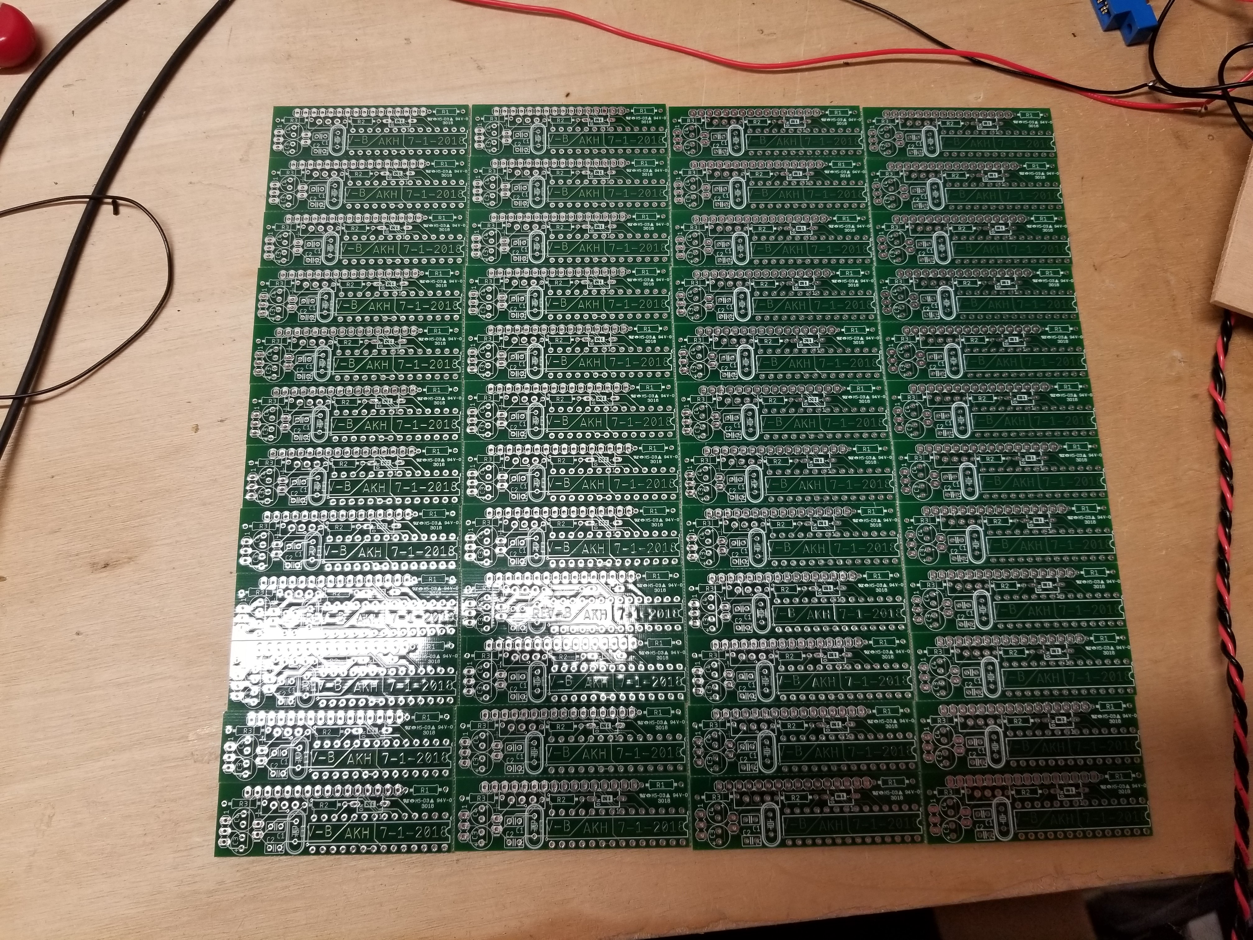
40 boards! I'm going to have lots of leftovers!
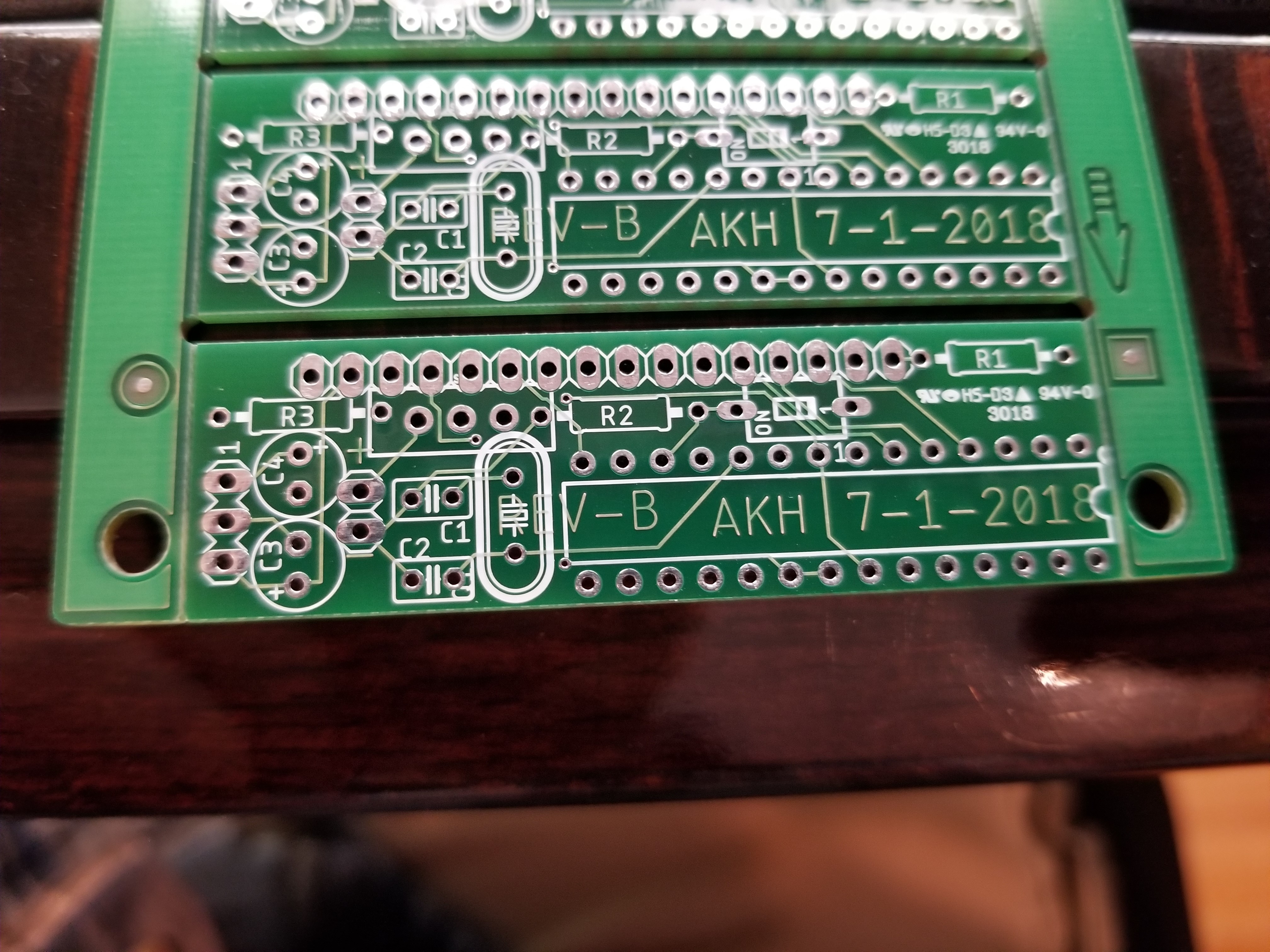
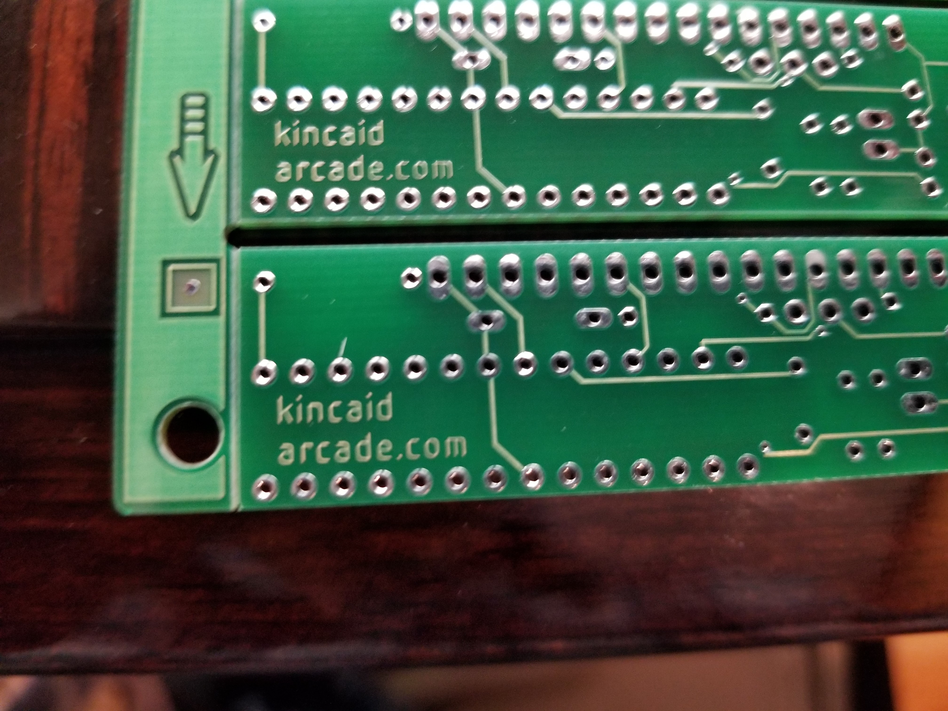
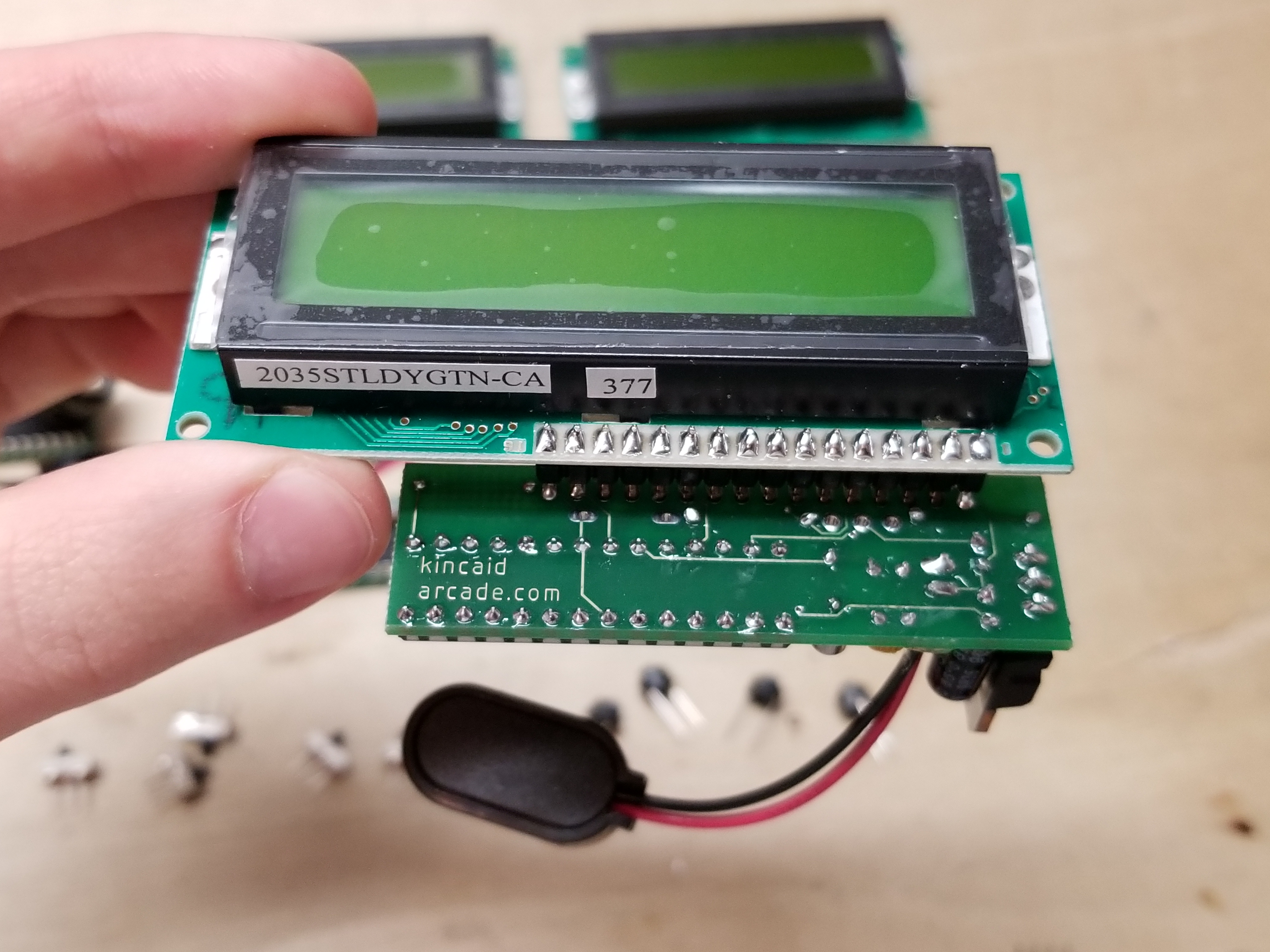
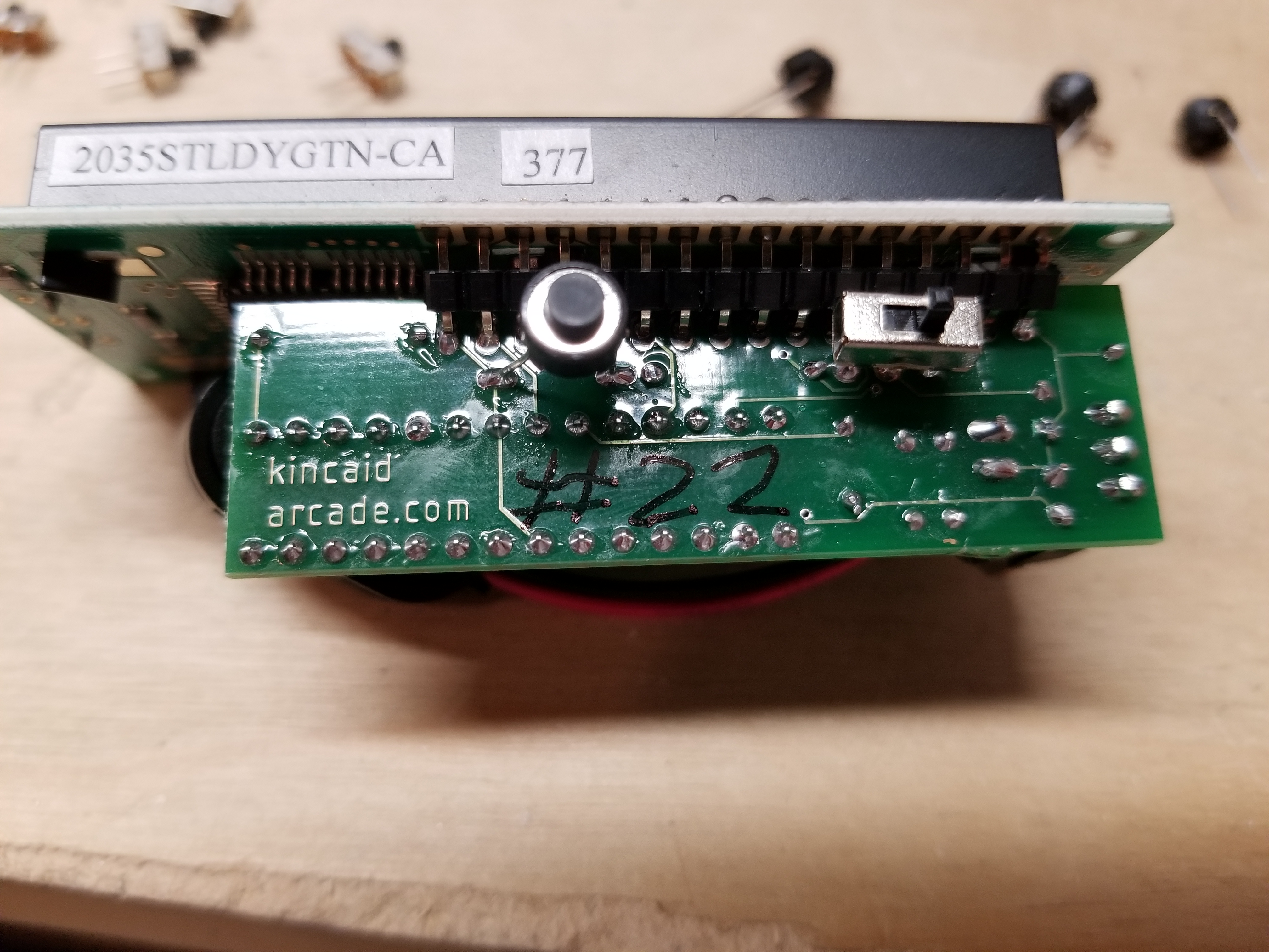
I made sure to properly credit myself, as always.
From there, I soldered one up and tested it. It did nothing. I soldered up another and it worked the first time. After some testing and many attempts to fix it, I just decided it was defective. Oh well.
Then, I started designing the case. I decided to do it in two parts, to simplify printing. The case for the REV-A would've been in three parts if I had finished it.
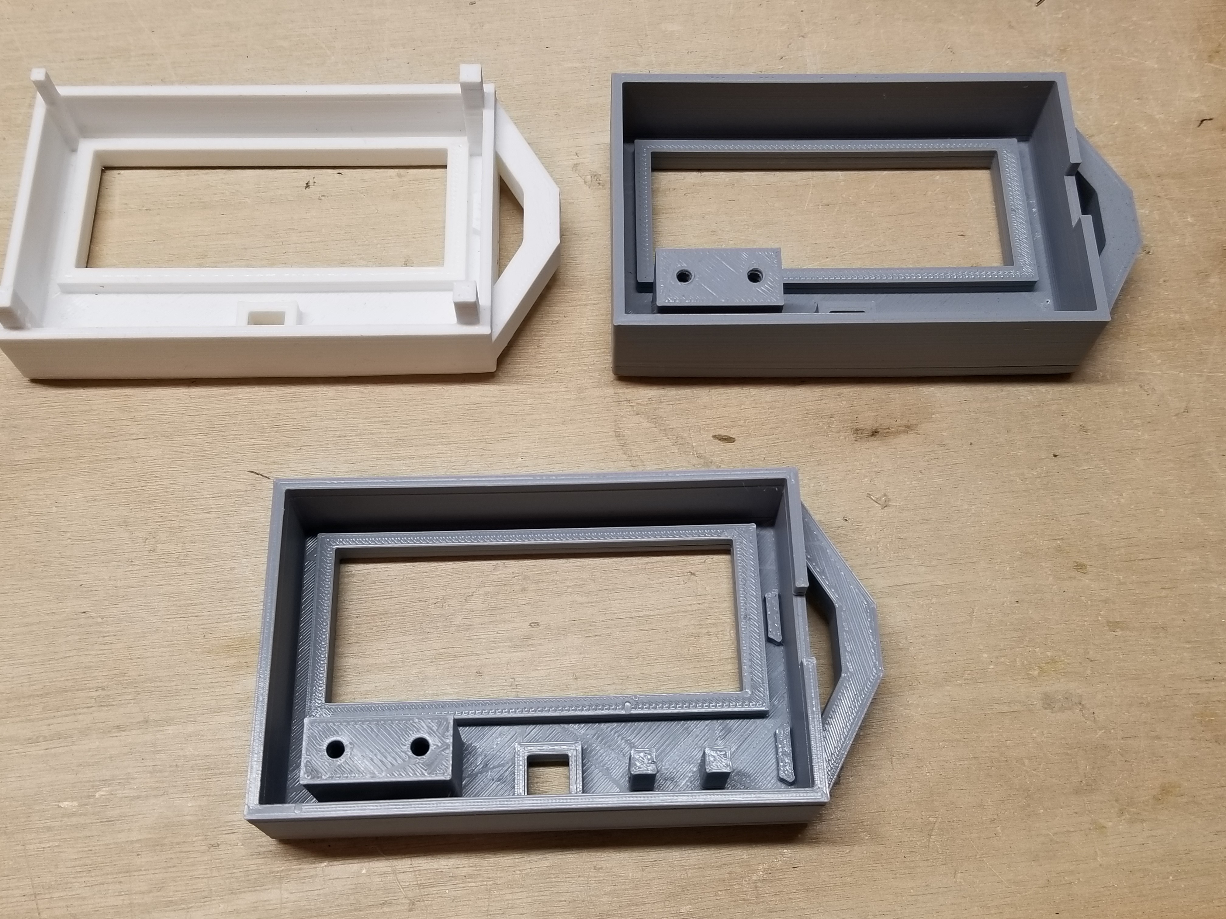
I went through around 9 different prototypes for the top and bottom of the case:
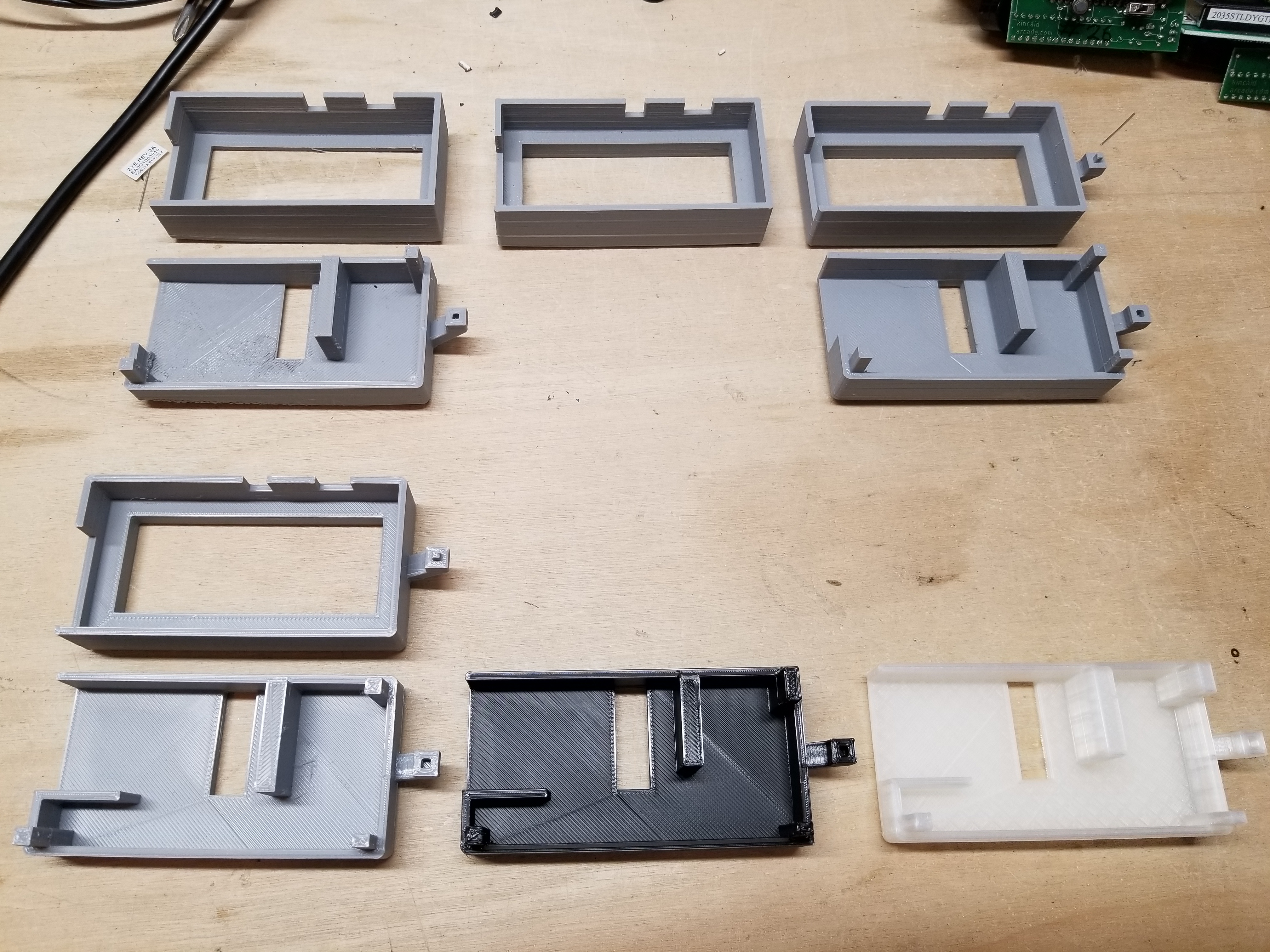
Revisions are in order from left to right, top to bottom. I did 4 revisions for the top, and 5 for the bottom.
The black case had some edges that I forgot to round. I fixed that before I started using my transluscent fillament. The fourth gray prototype of the top part of the case had fixed all of the issues. The bottom finally had all its issues fixed by the time of the translucent case.
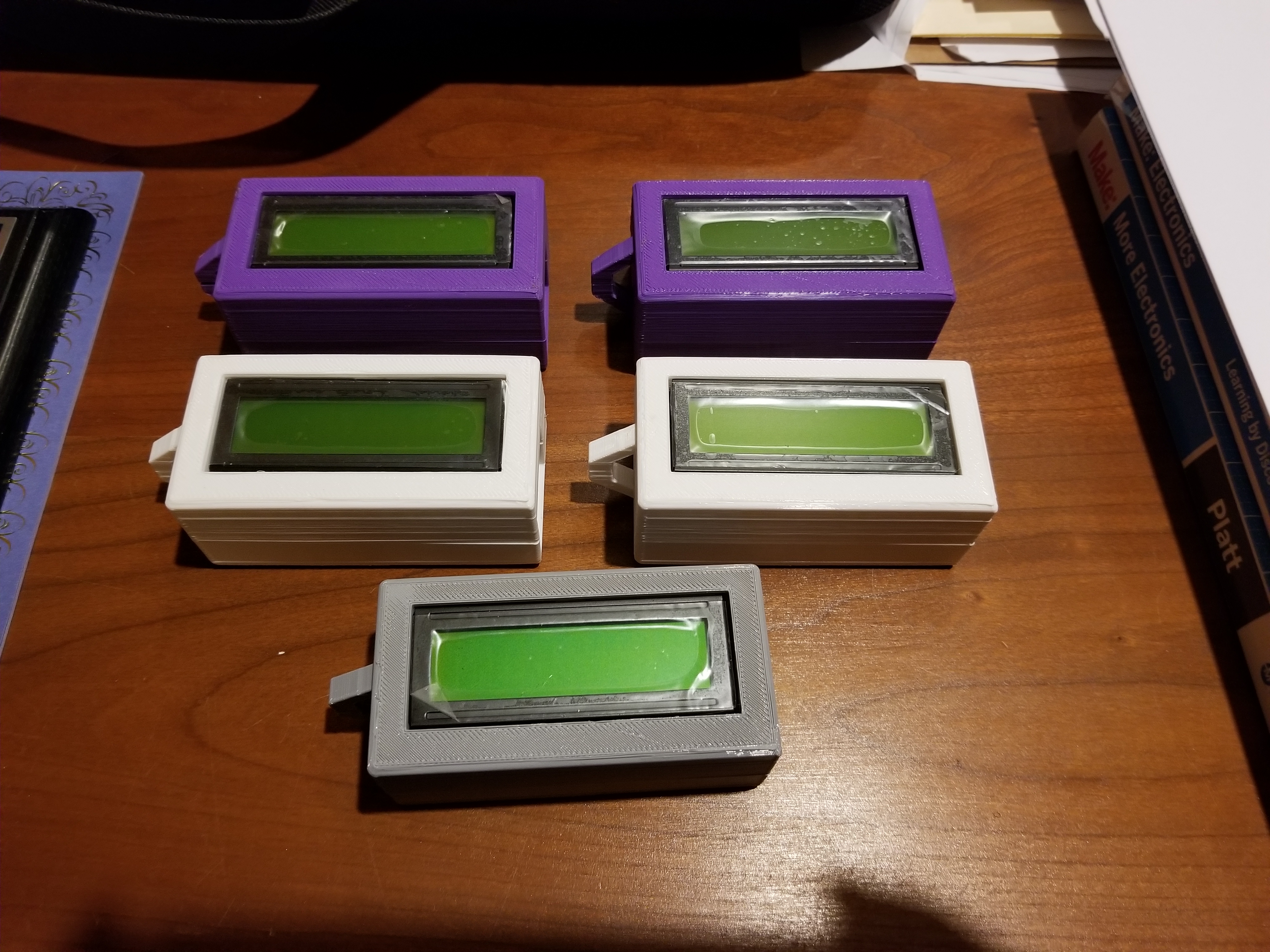
I've made many more Pocket Encouragement Devices since the time I've started the project. I've mostly just been giving them away to friends and family.
Here are images of some of the many I've made and gave away:

Lastly, I shot a video of one doing its thing a long time back. Sorry about the poor angle of the video.
I also shot a video of serials 22 and 23 displaying verses. It is down closer to the bottom of the page, here.
This was one of the earlier case revisions. Notice the gap in the keychain attachment part.
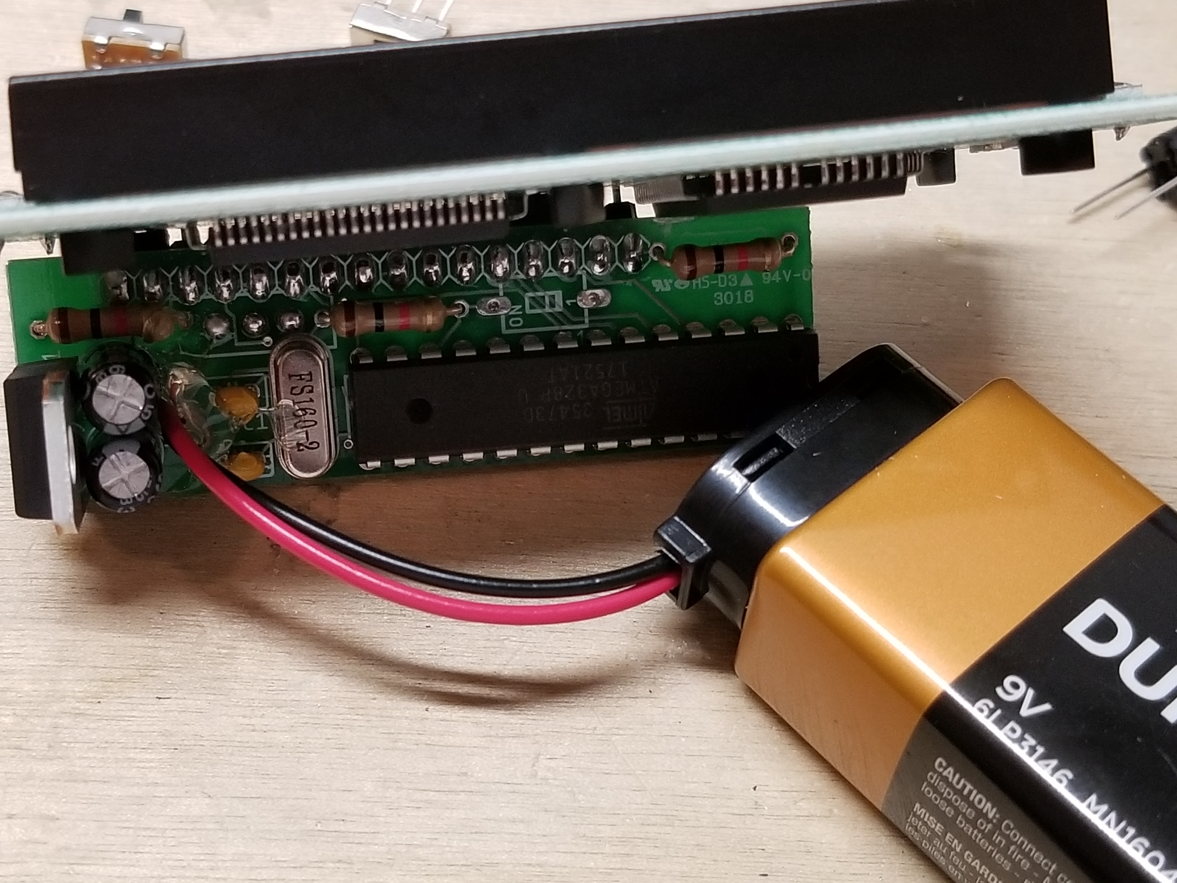
The finished version of the code has a total of 79 Bible verses of the ESV (English Standard Version) translation on it. If I did the project again, I'd probably use the NIV (New International Version) translation instead. When compiled, the code takes up a total of 32,252 bytes, 4 bytes short of the Atmega328p-pu's flash memory. The uncompiled code is 4770 lines long.
At one point, every byte was used. I have since changed it, and it is now more efficient and it has more Bible verses. This program was my first program to make effective use of loop counters. There are no delays anywhere in the code.
If you are interested in the code, you can view it here.
If you choose to modify it, please add your name to the header at the top, but don't remove my name or Kincaid Arcade.
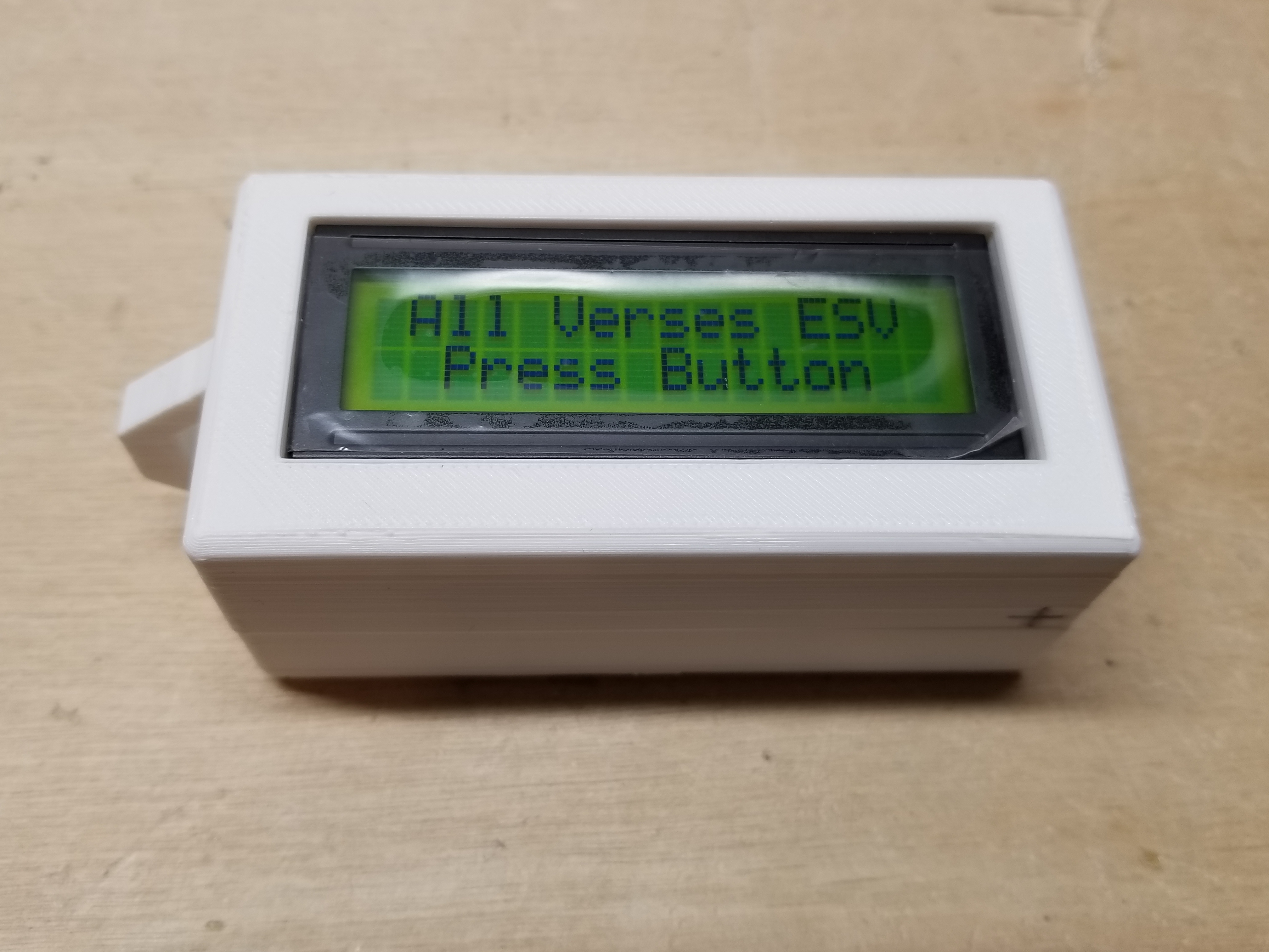
How to use a Pocket Encouragement Device
I designed these to be relatively simple. That included limiting the number of controls.
In an earlier design, I planned on having several extra buttons to allow the person to select a random verse from 'hope', 'encouragement', and 'peace', among others, but I decided against it.
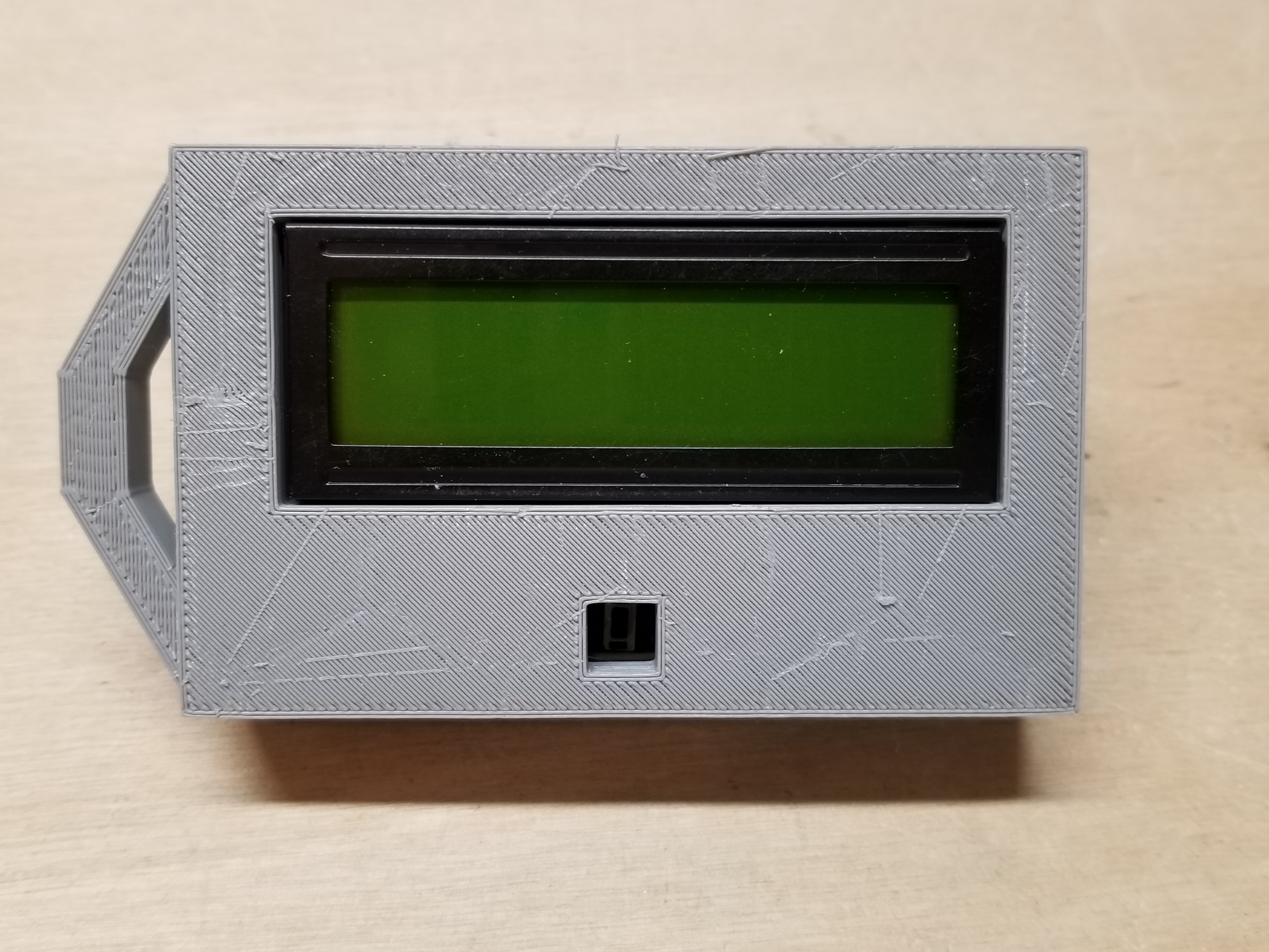
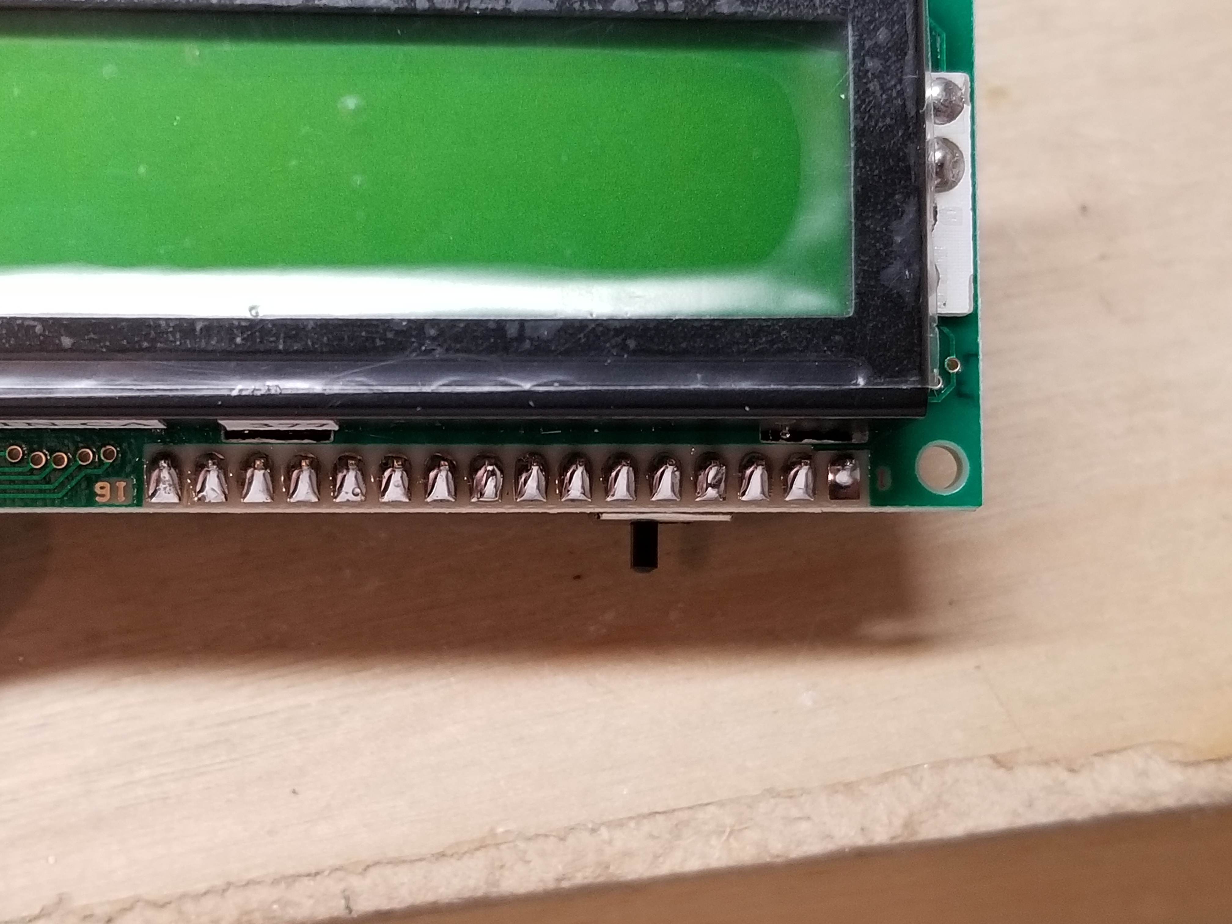
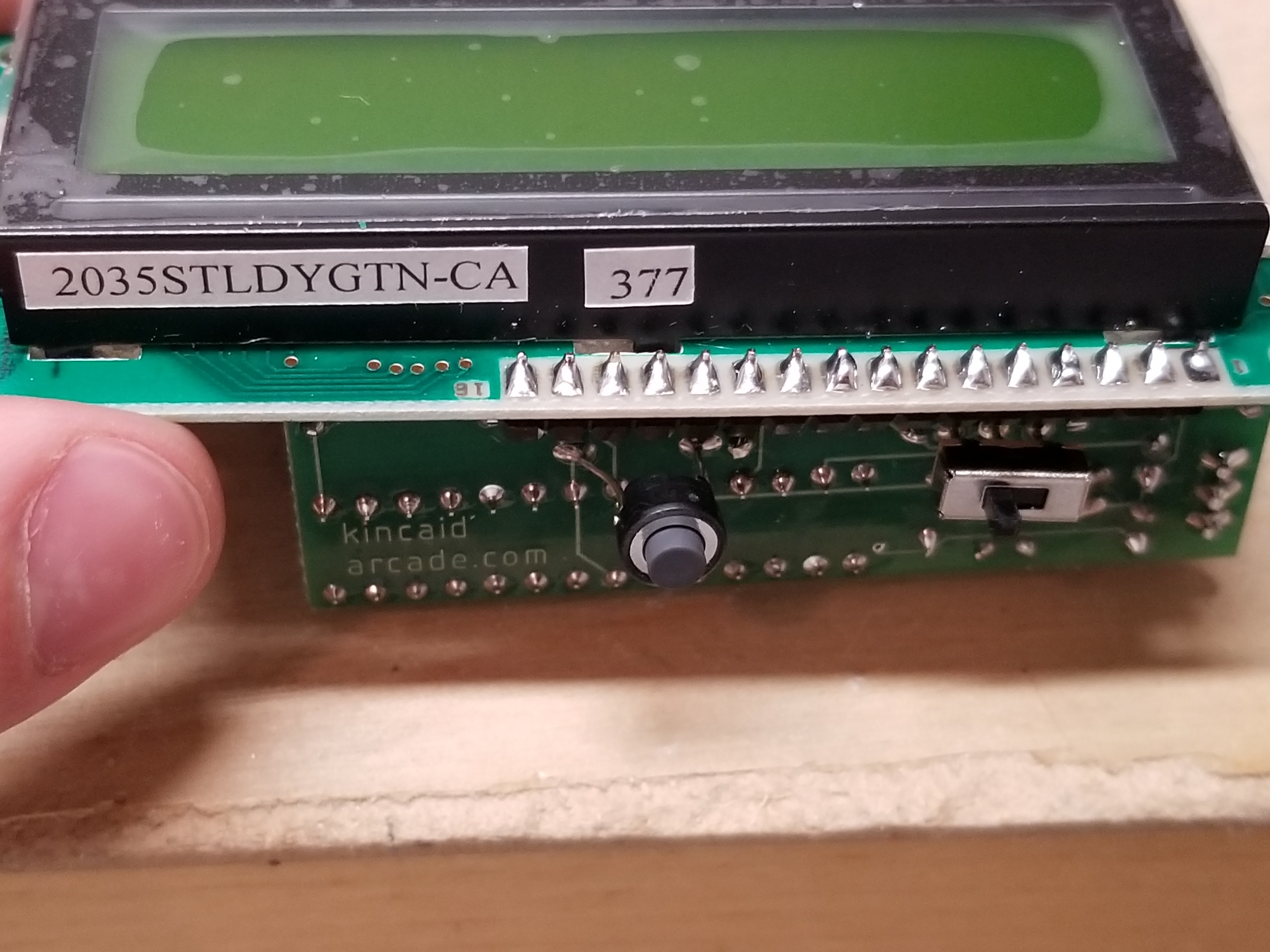
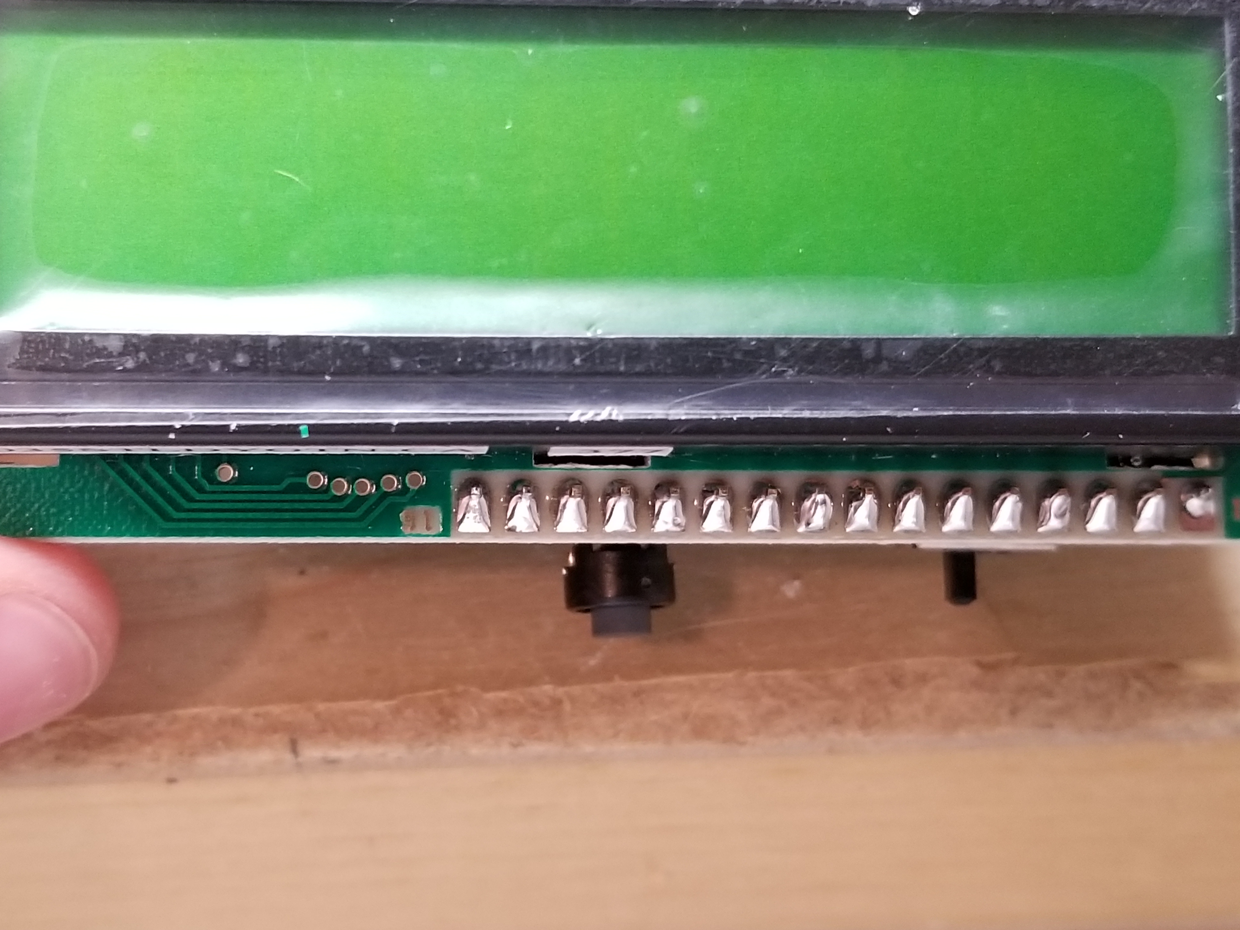
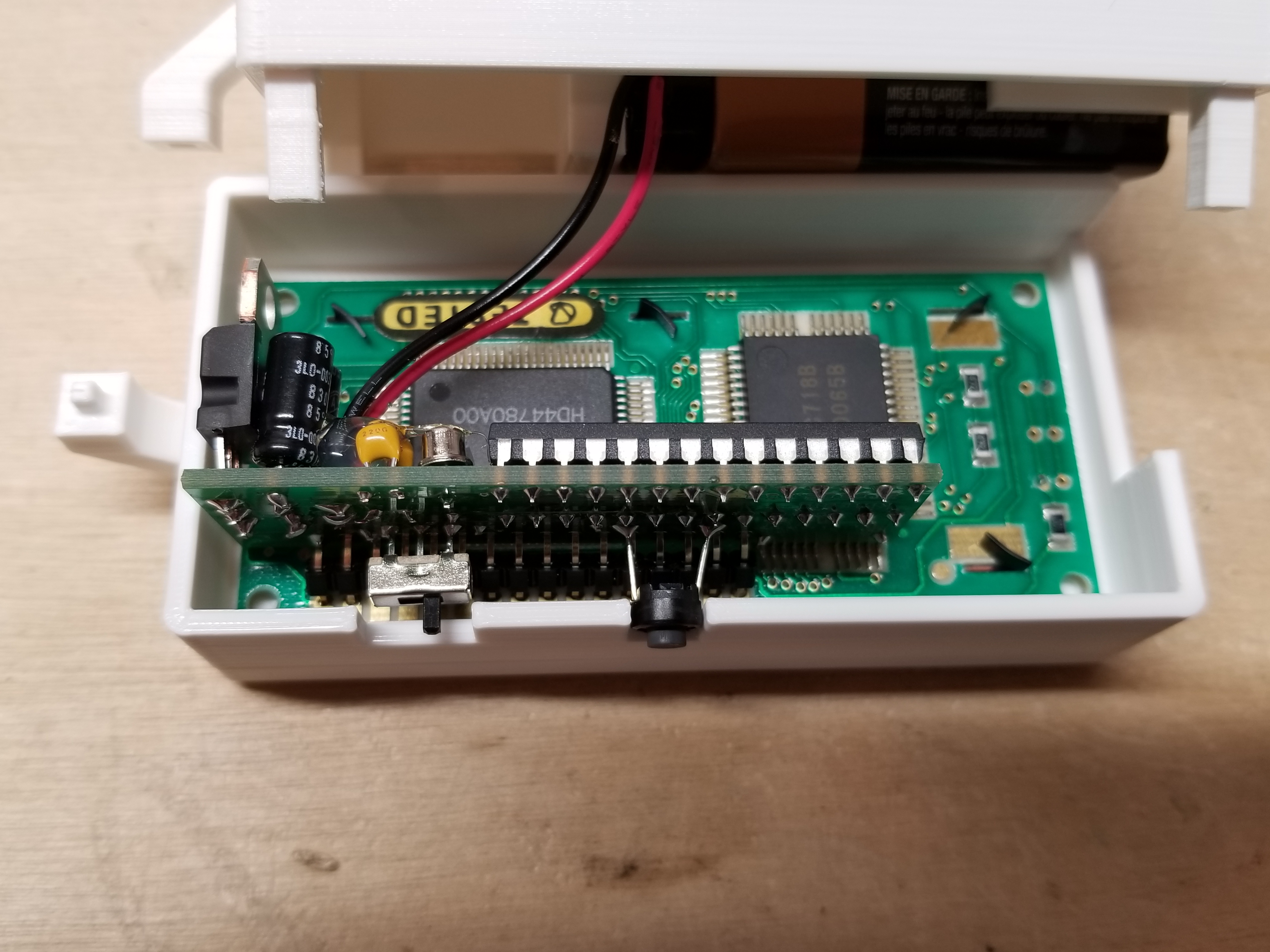
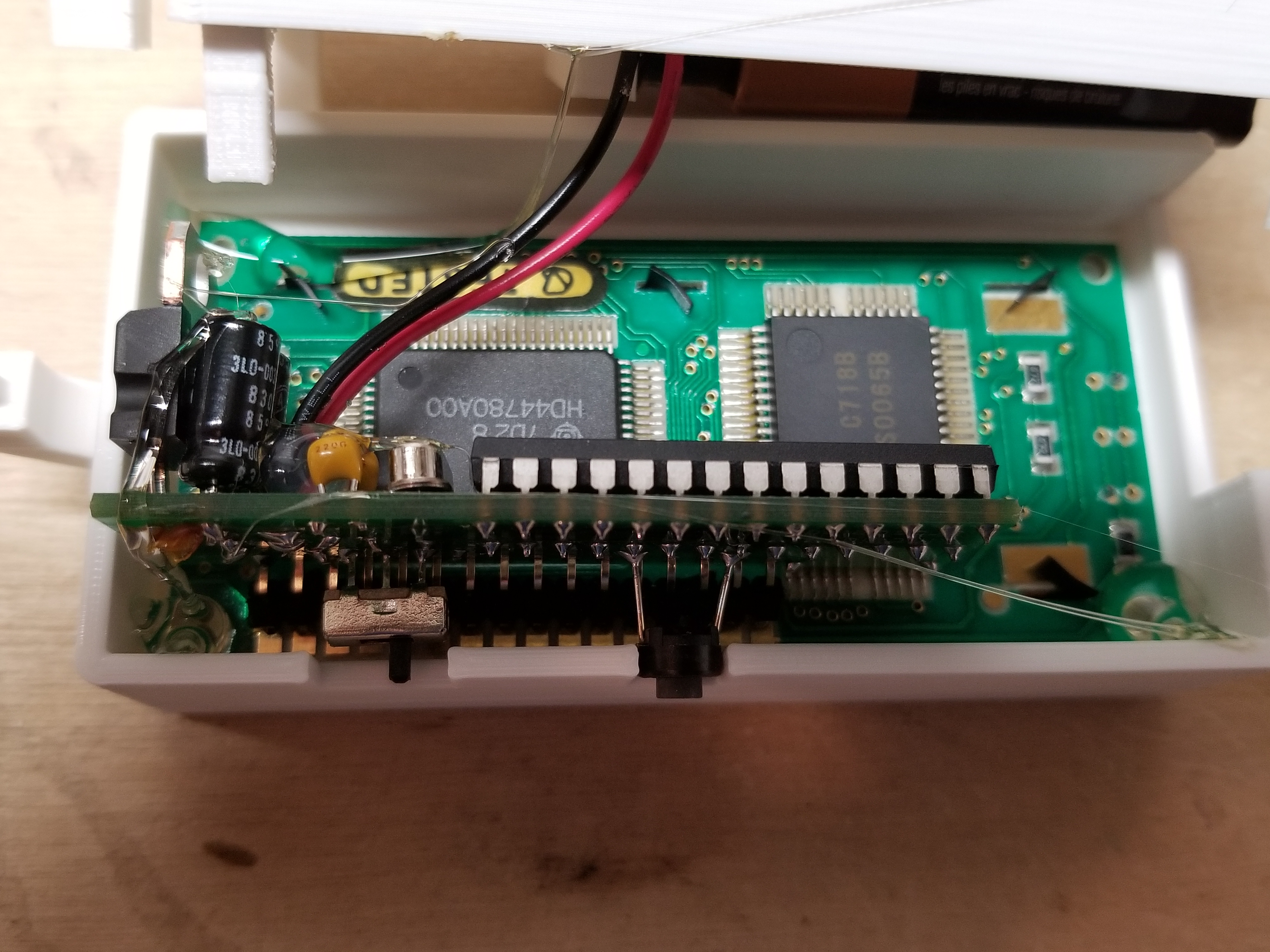
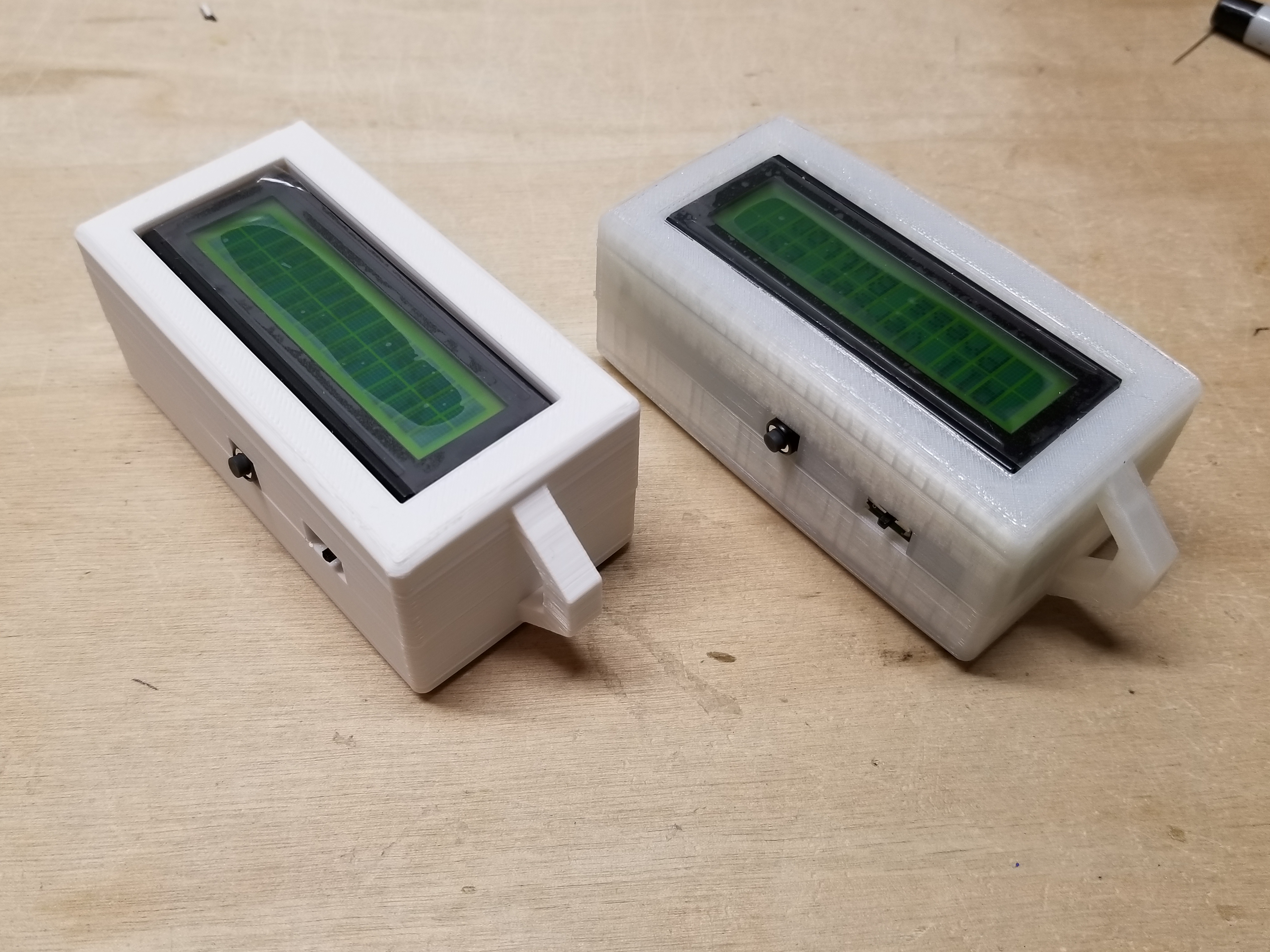
In the end, there were only two controls: a switch and a button.
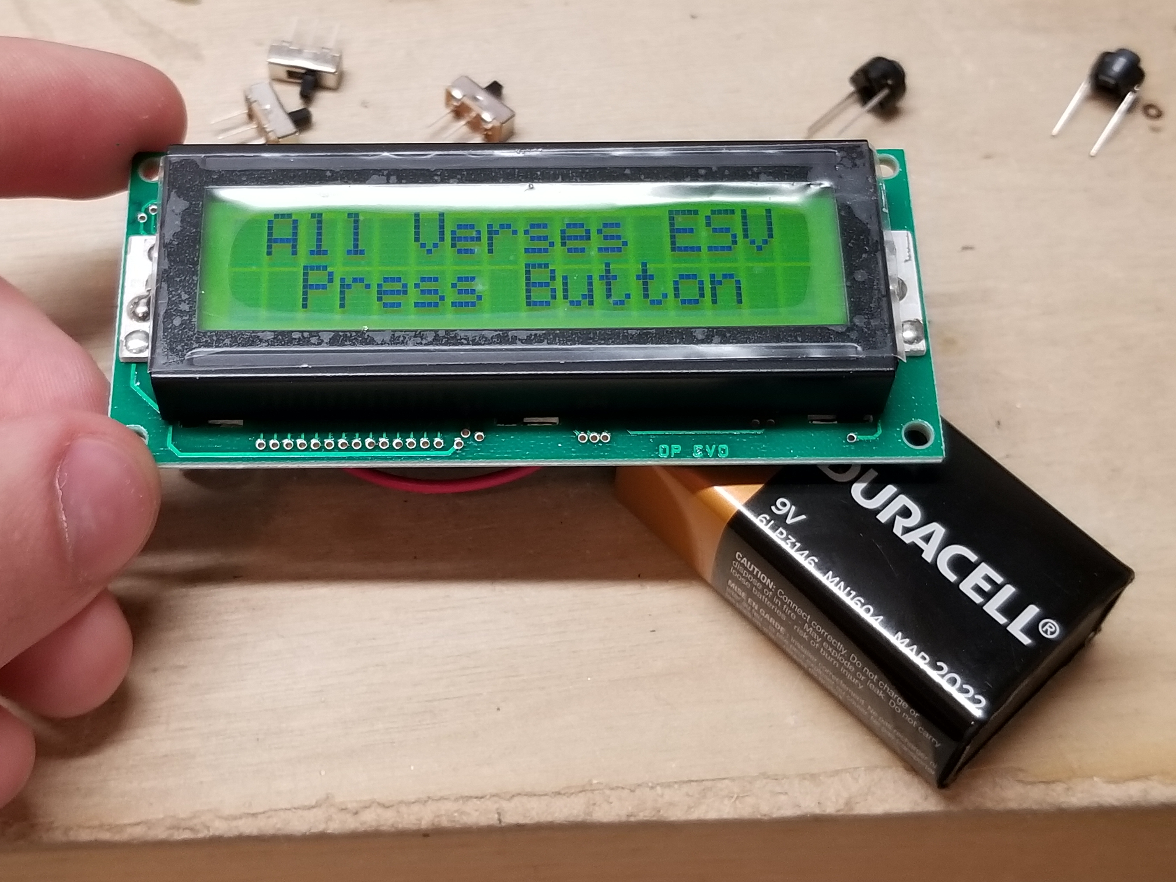
You can see that here:

The switch is the on/off switch. If it is in the 'left' position, the device is on. 'Right', and it is off.
Pressing the button tells the device to display a verse. Pressing it again will give you a different verse.
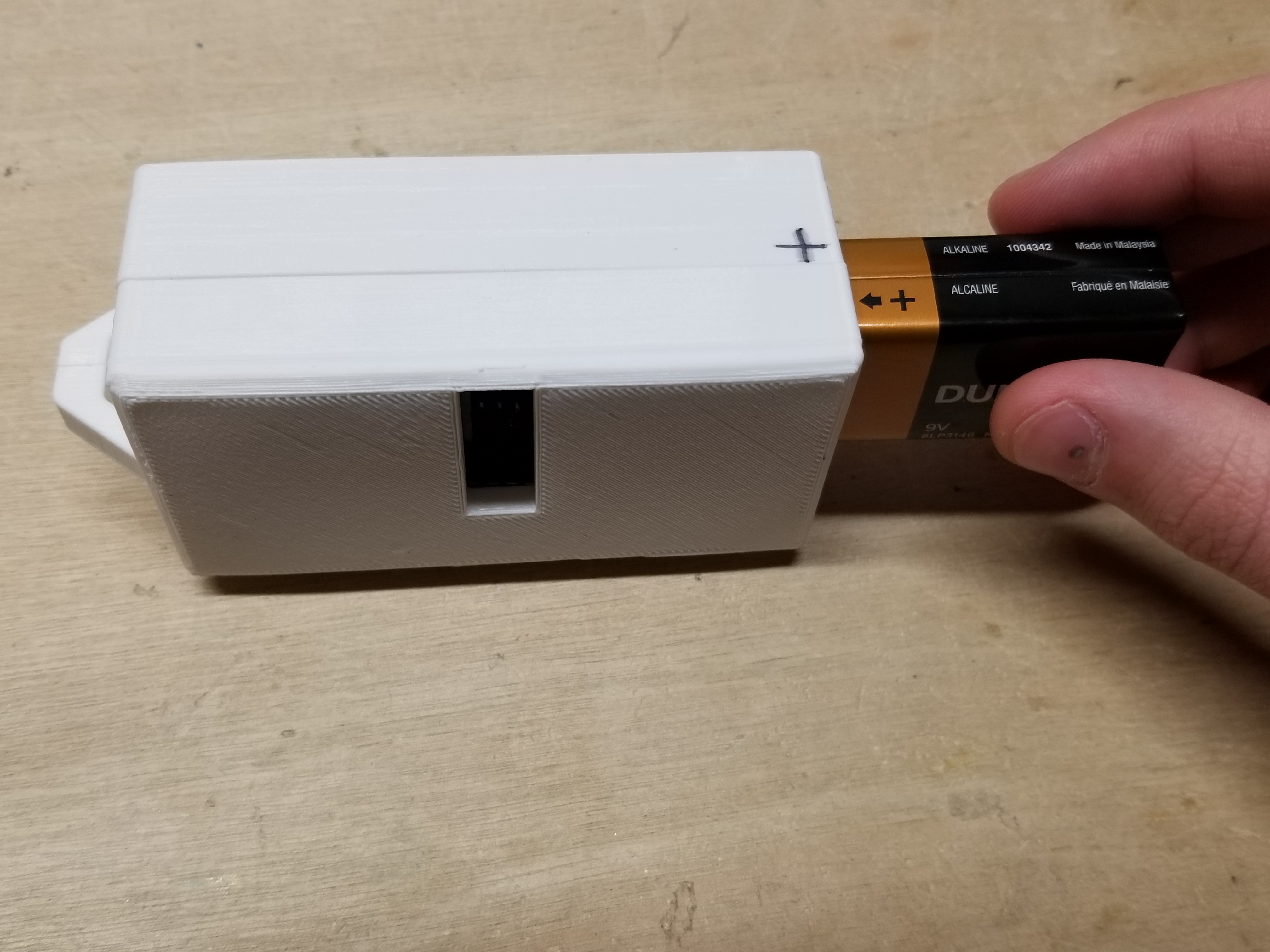
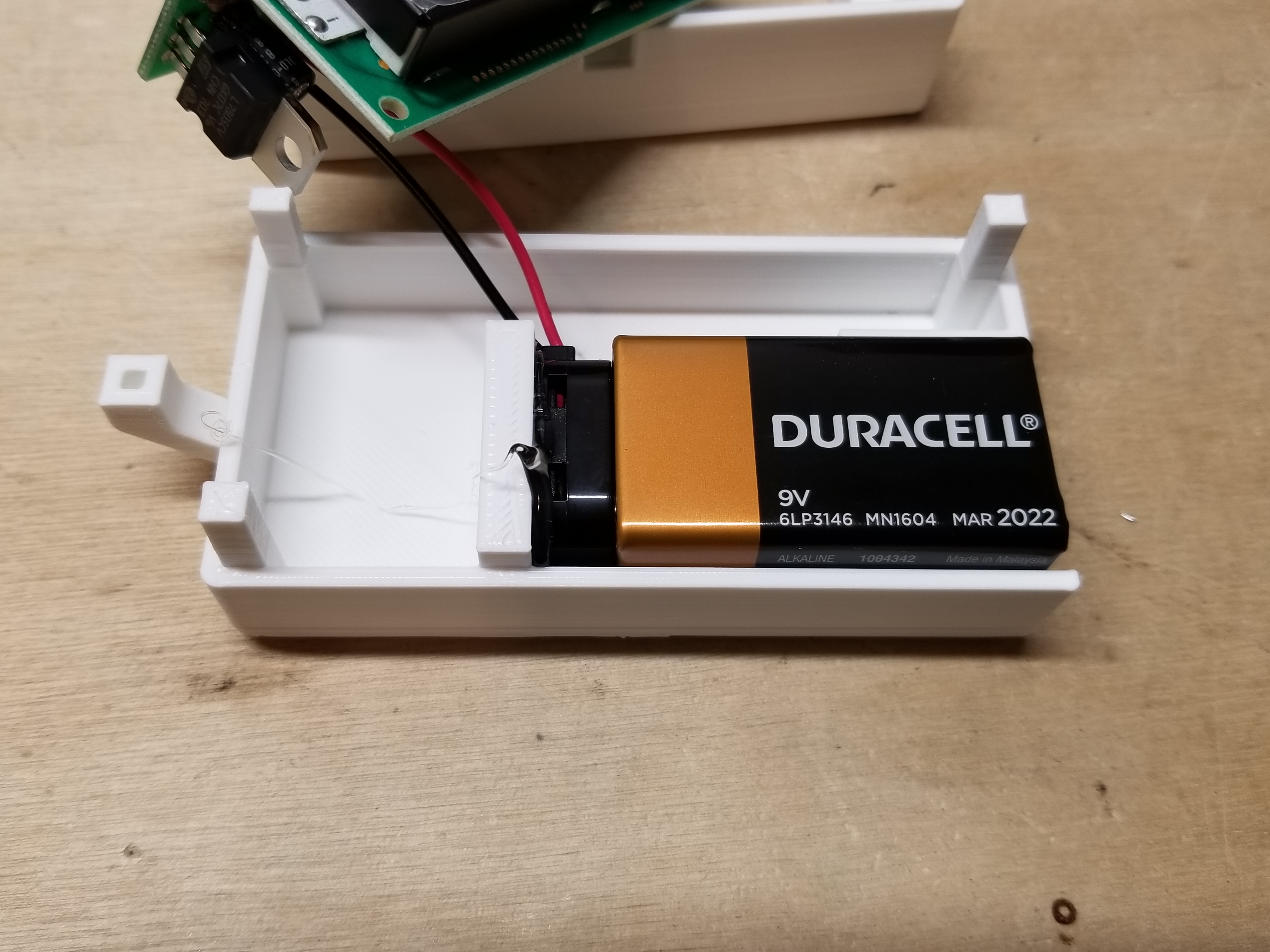
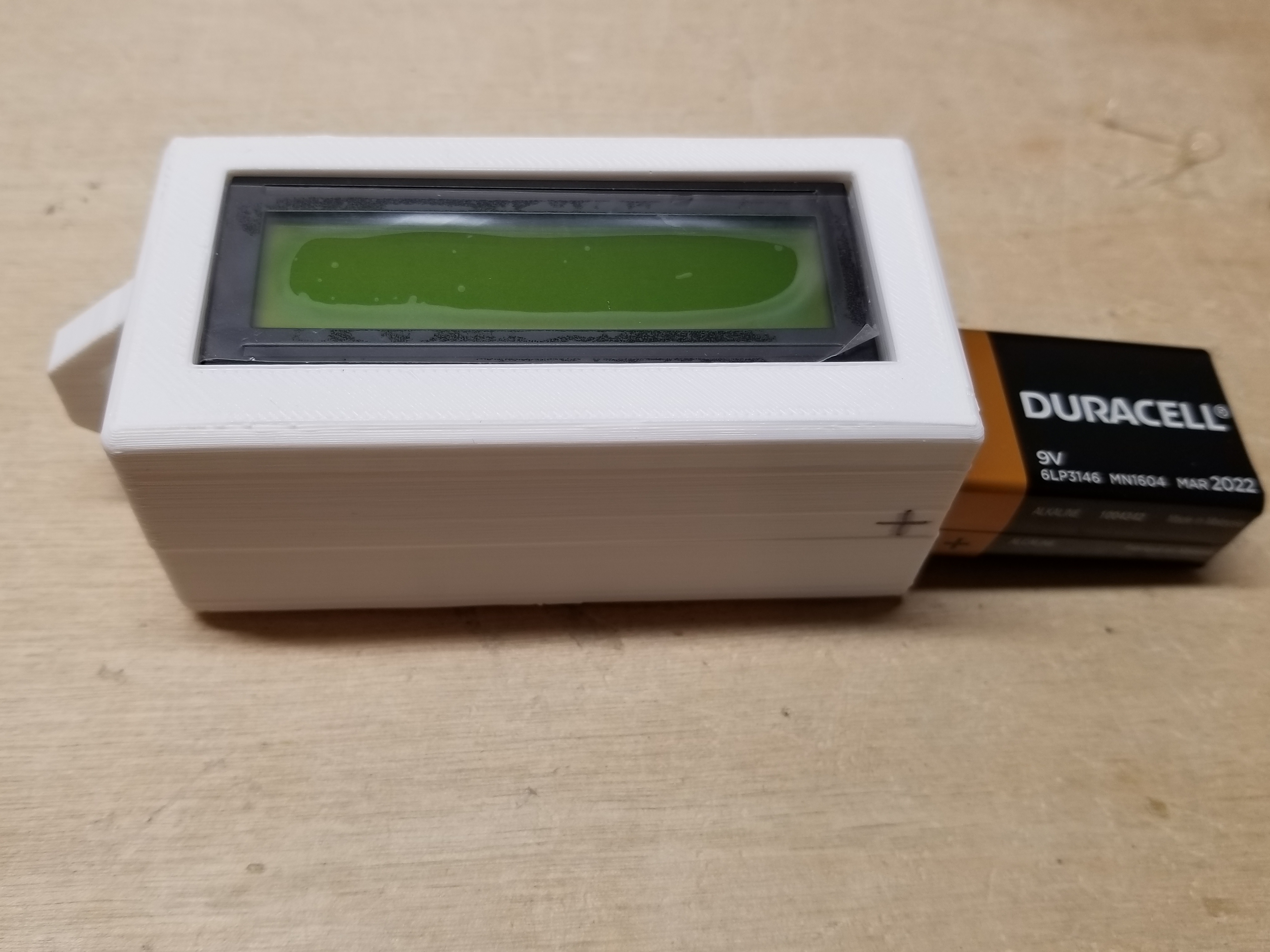
Inserting/removing the battery
To insert the battery, match the '+' on the battery with the '+' on the case, and push it in. There will be a 'click' when it is in all the way.
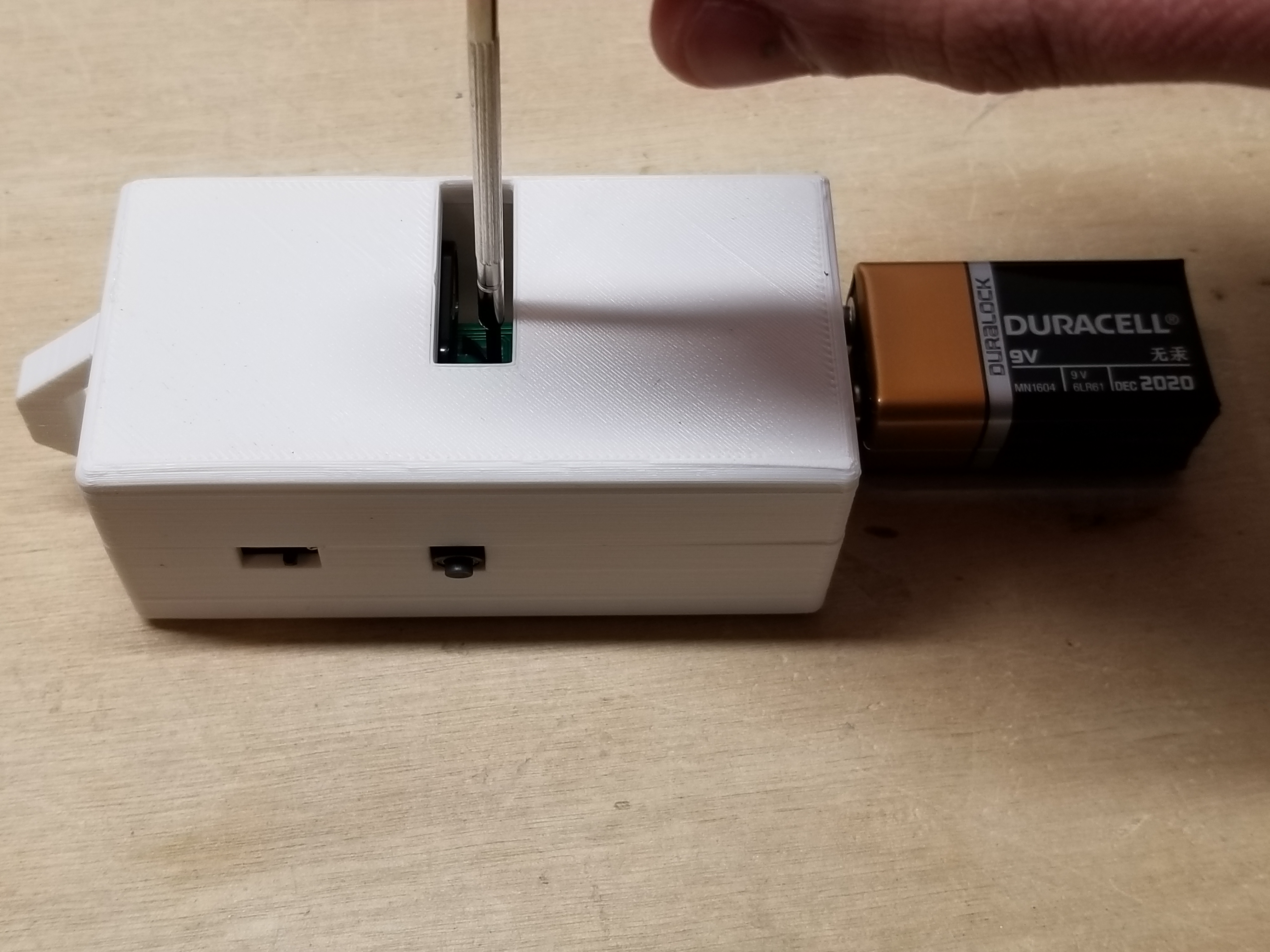
To remove the battery, flip the device over, and stick a screwdriver in the hole in the bottom. Aim between the top of the battery and the black thing beyond it.
Like this:
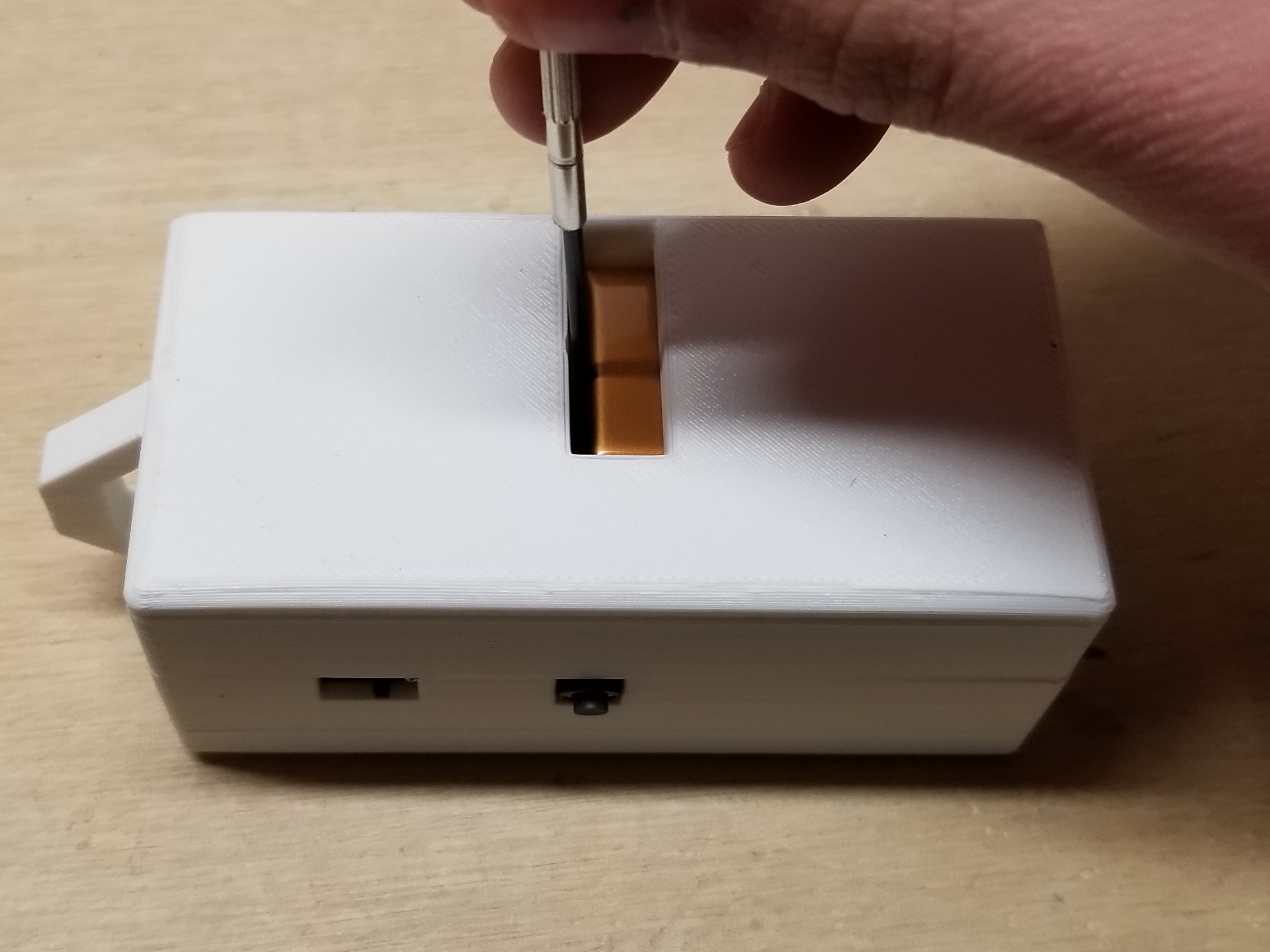
Then, all you have to do is push, and the battery will go flying.
Wiggling the screwdriver back and forth as you push will help, too.
How I assemble the Pocket Encouragement Devices
As you can probably tell, I have assembled many of these devices over the course of the past year or so. I will show you how I assemble them, for your viewing entertainment.
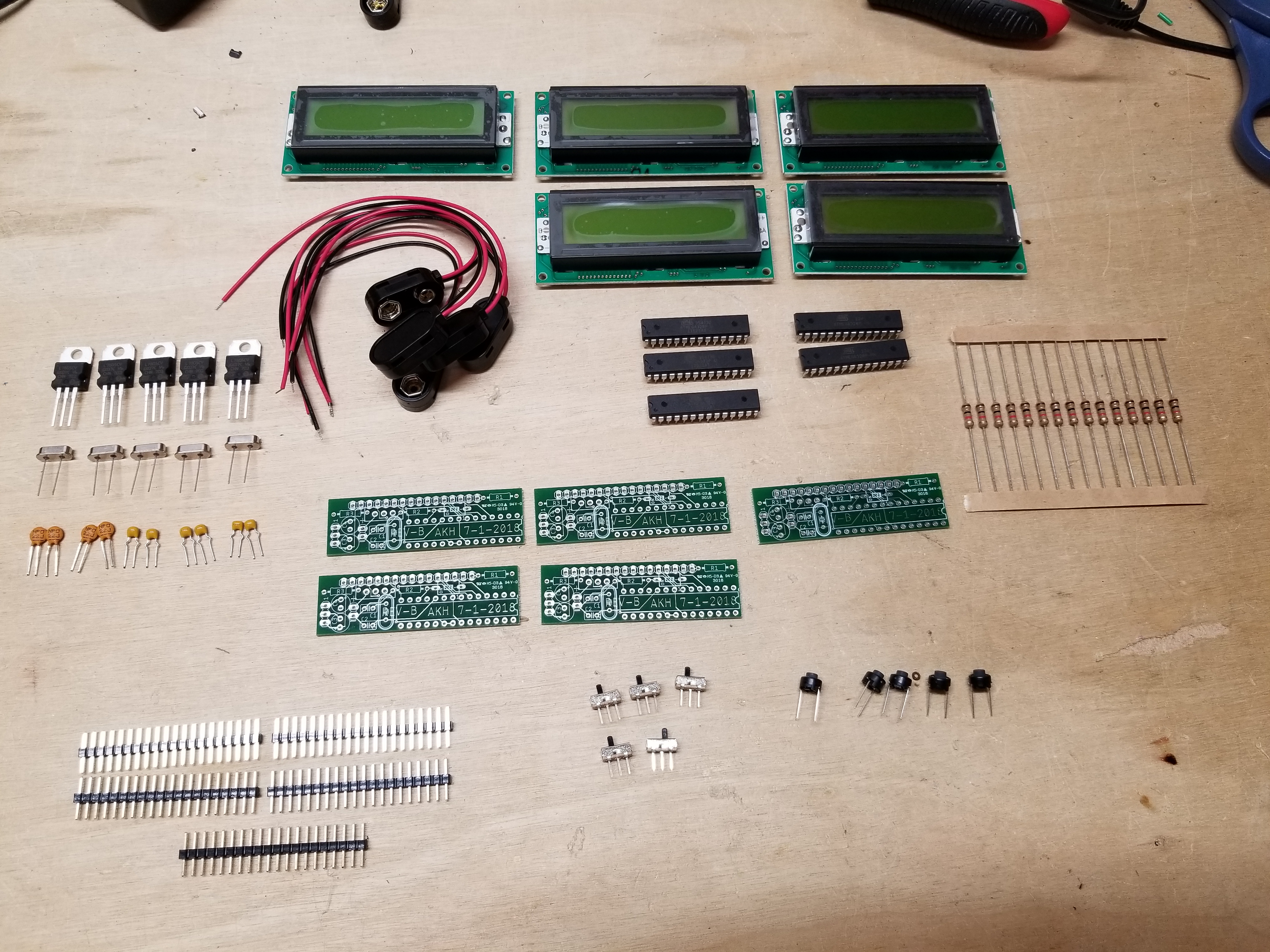
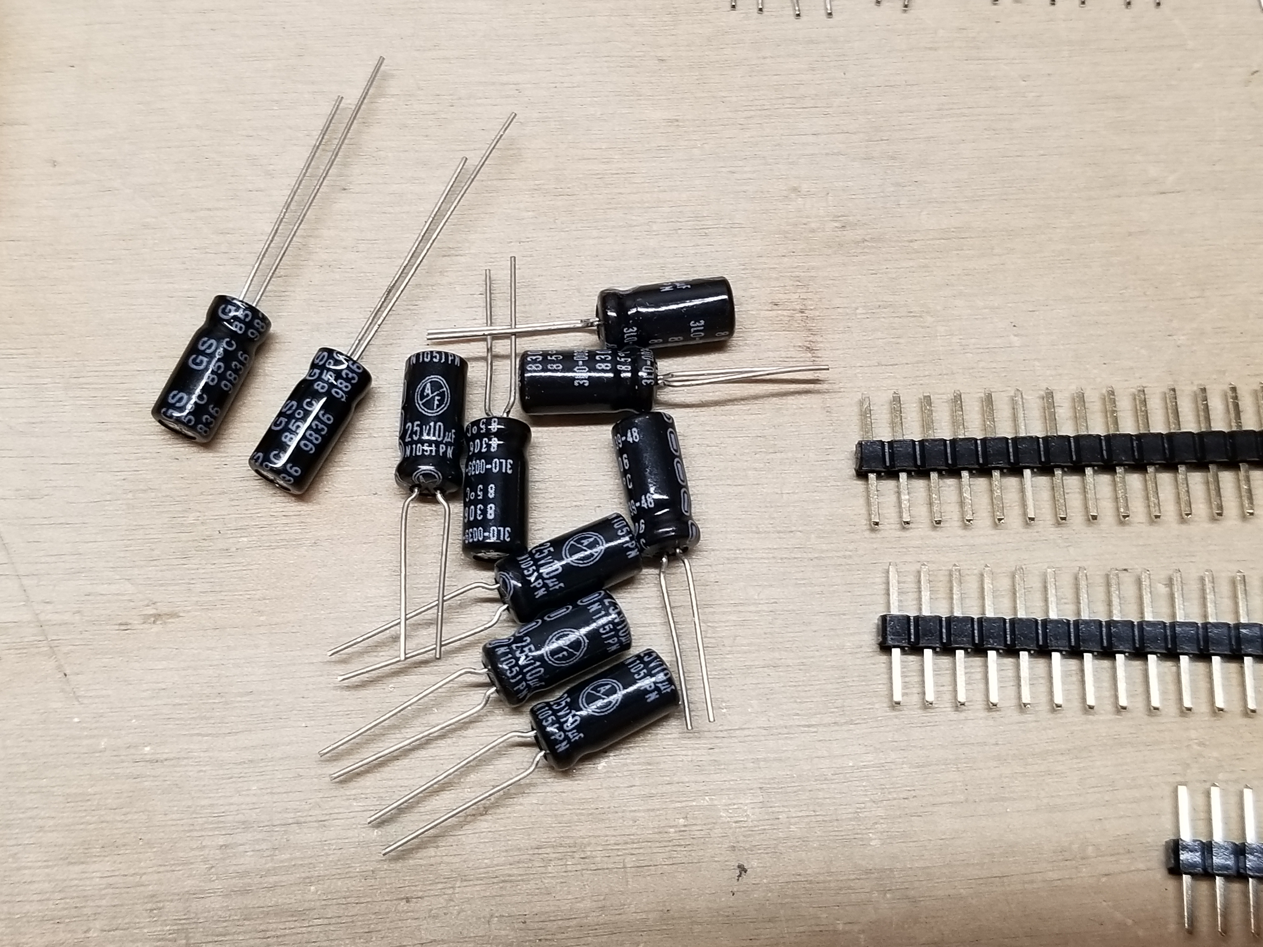
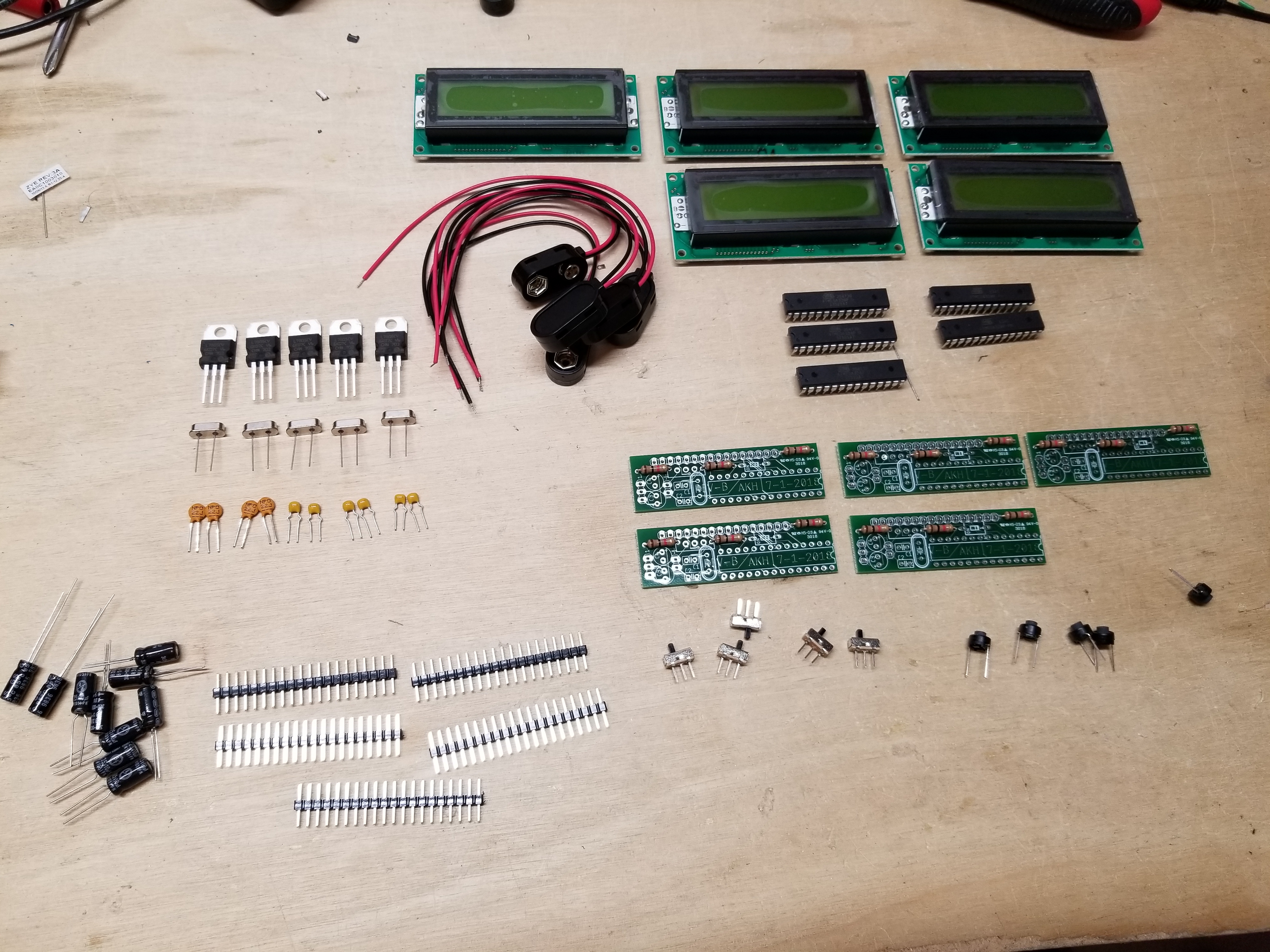
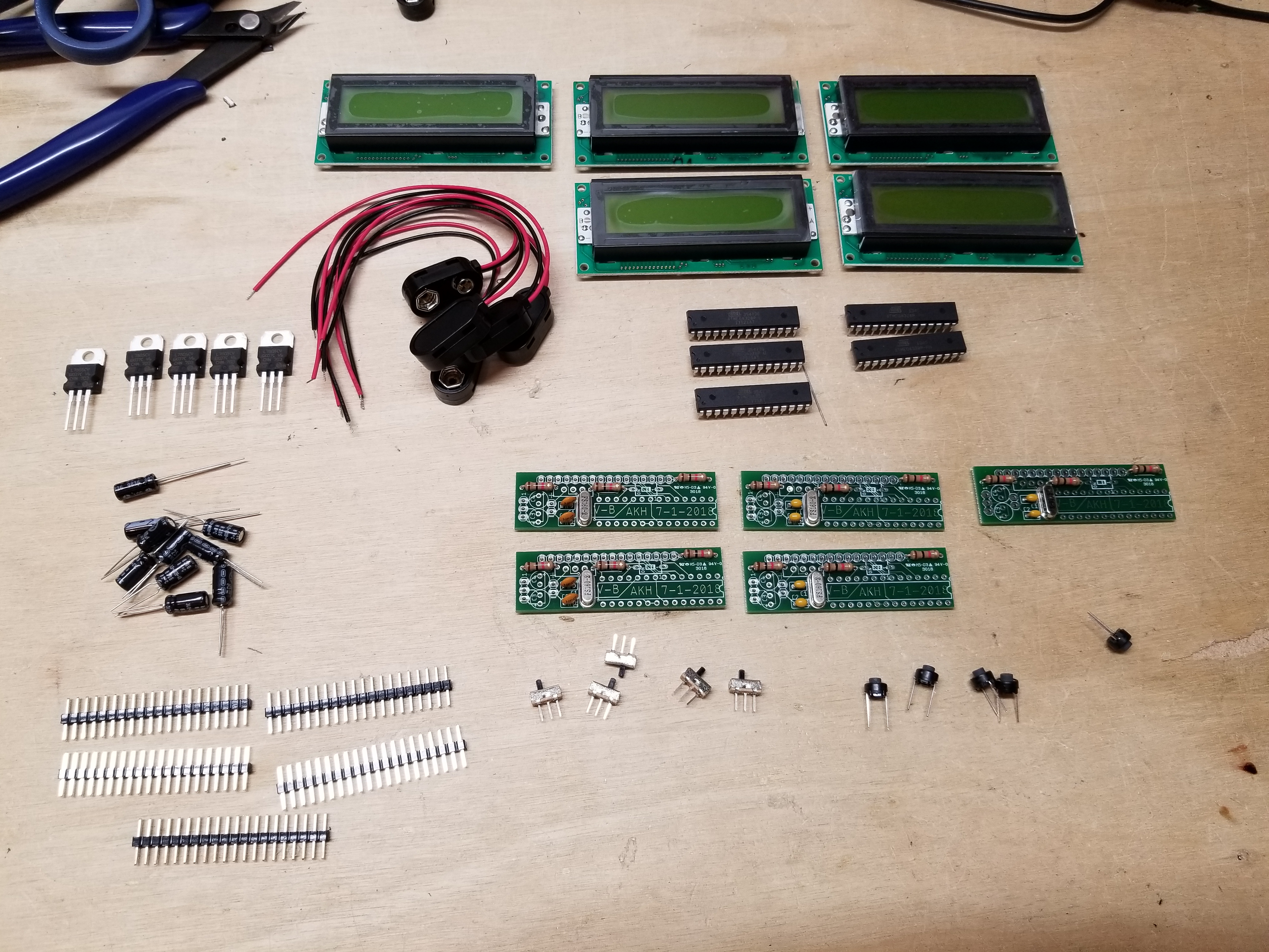
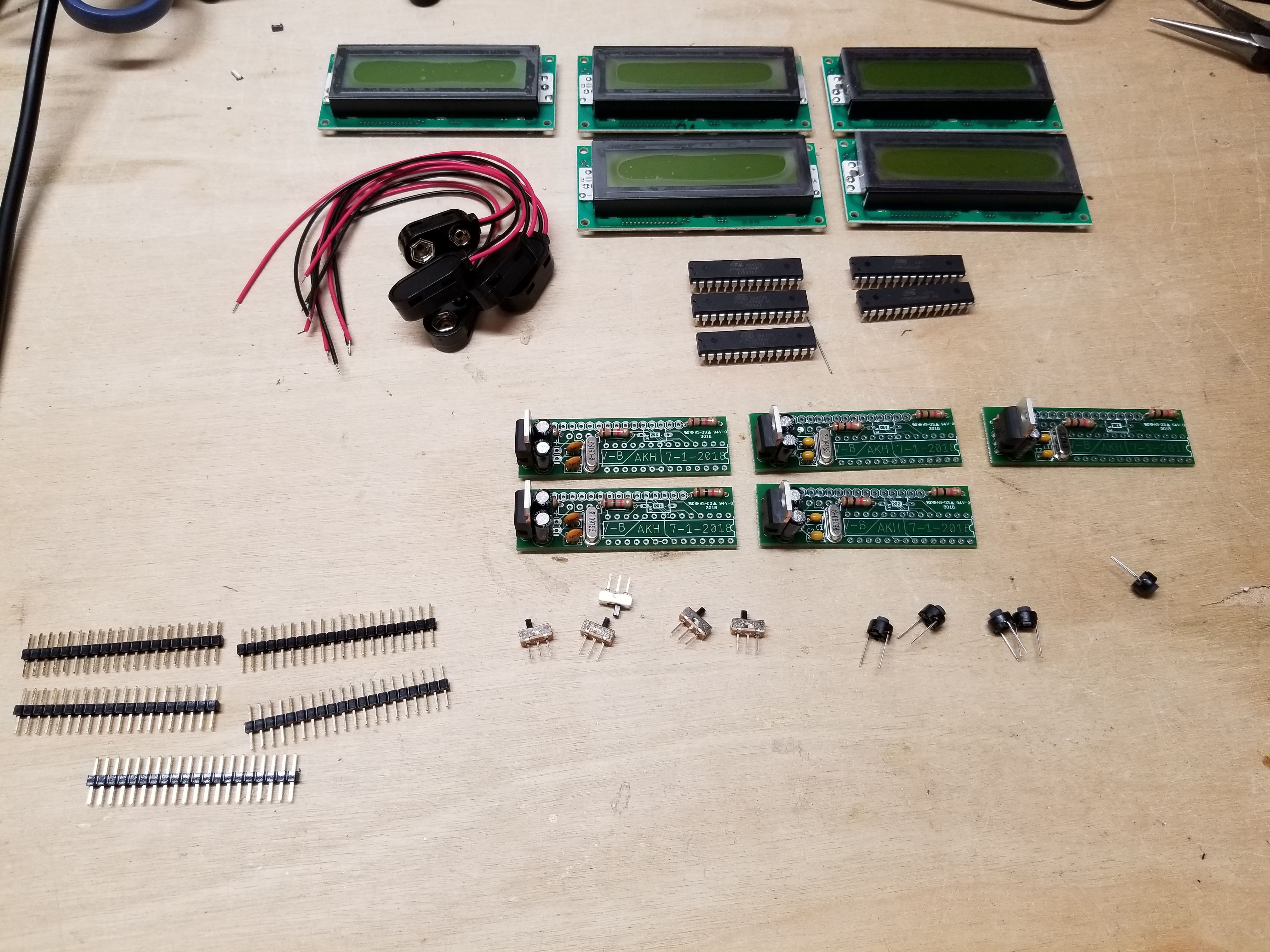
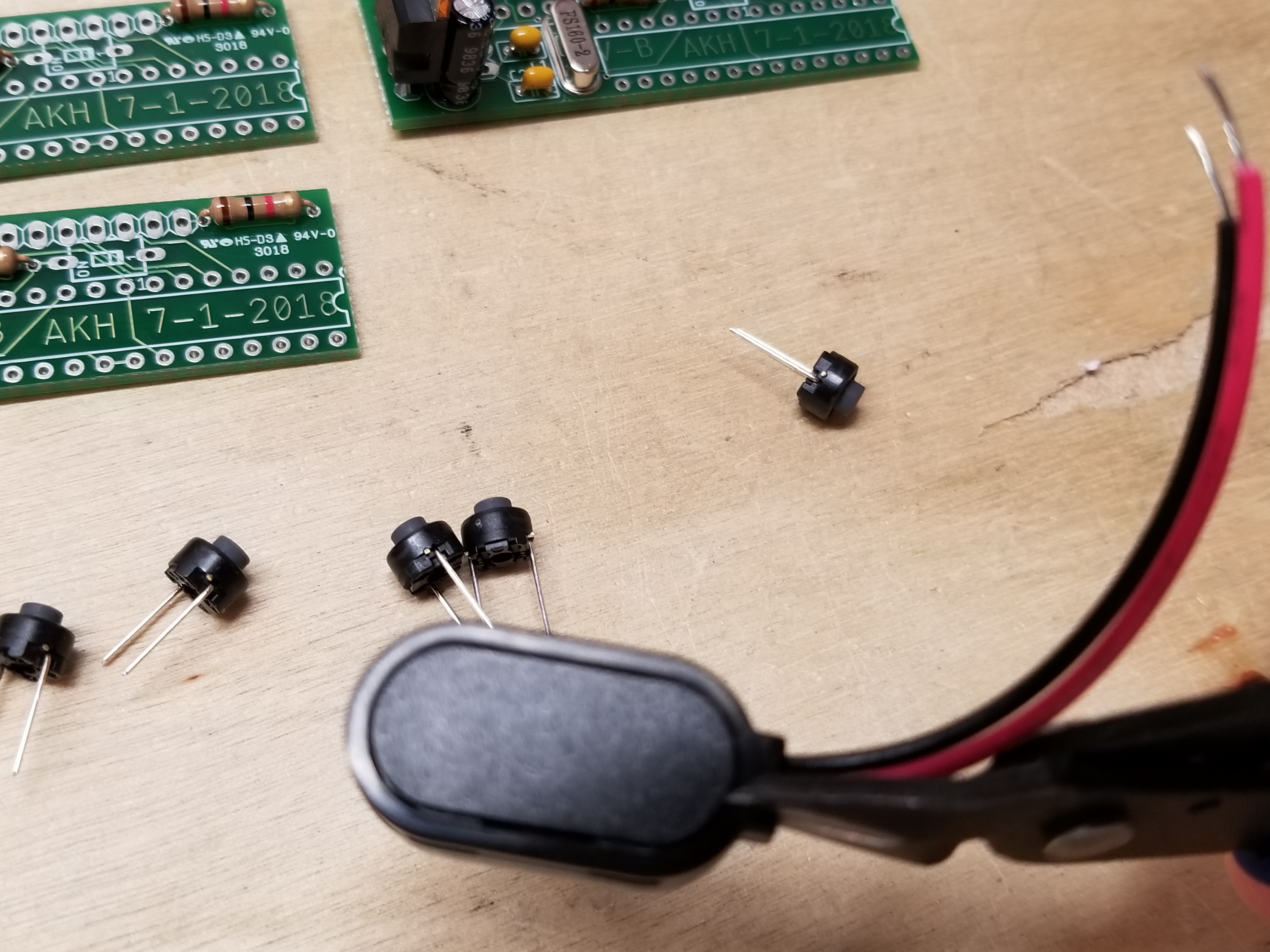
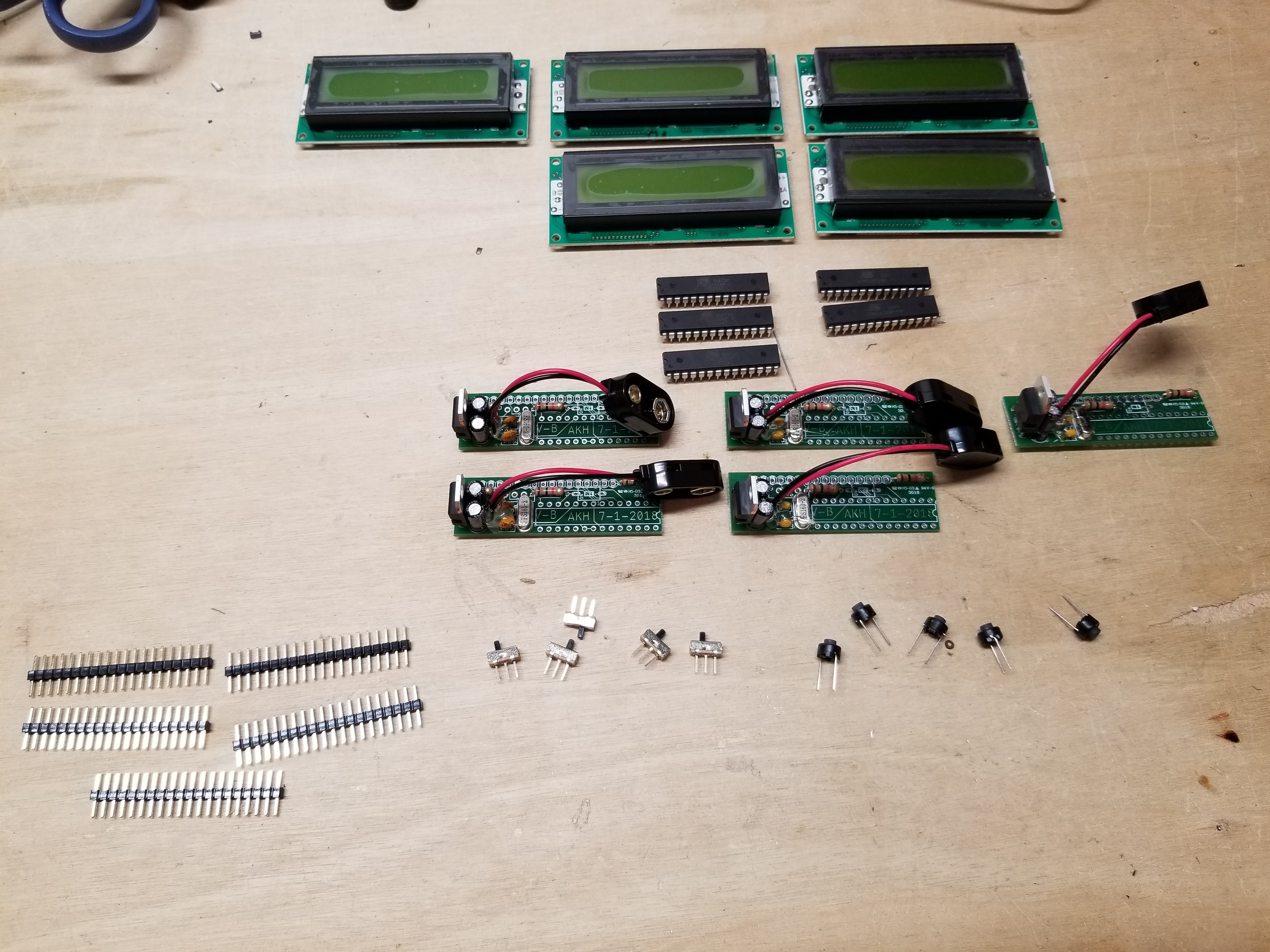
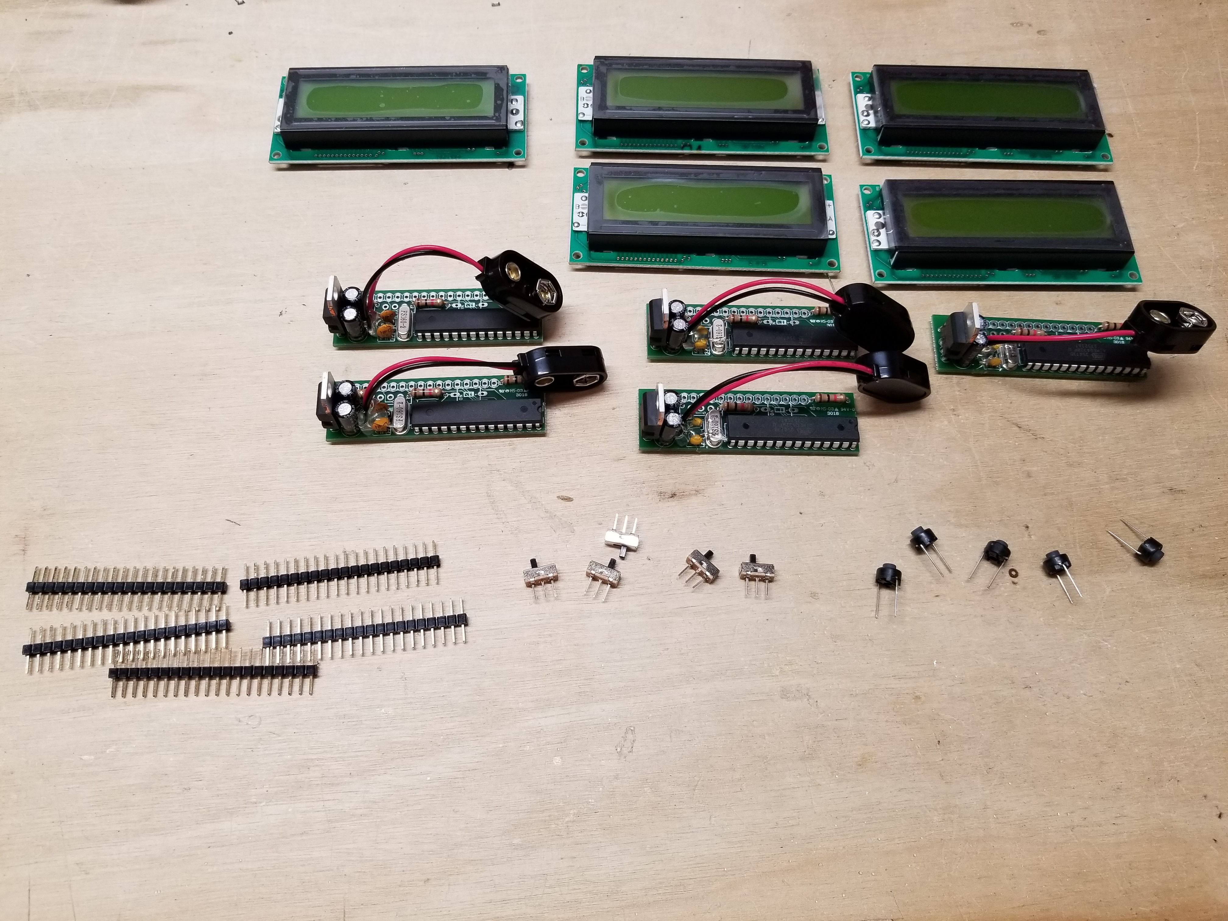
First, I start by gathering the parts.
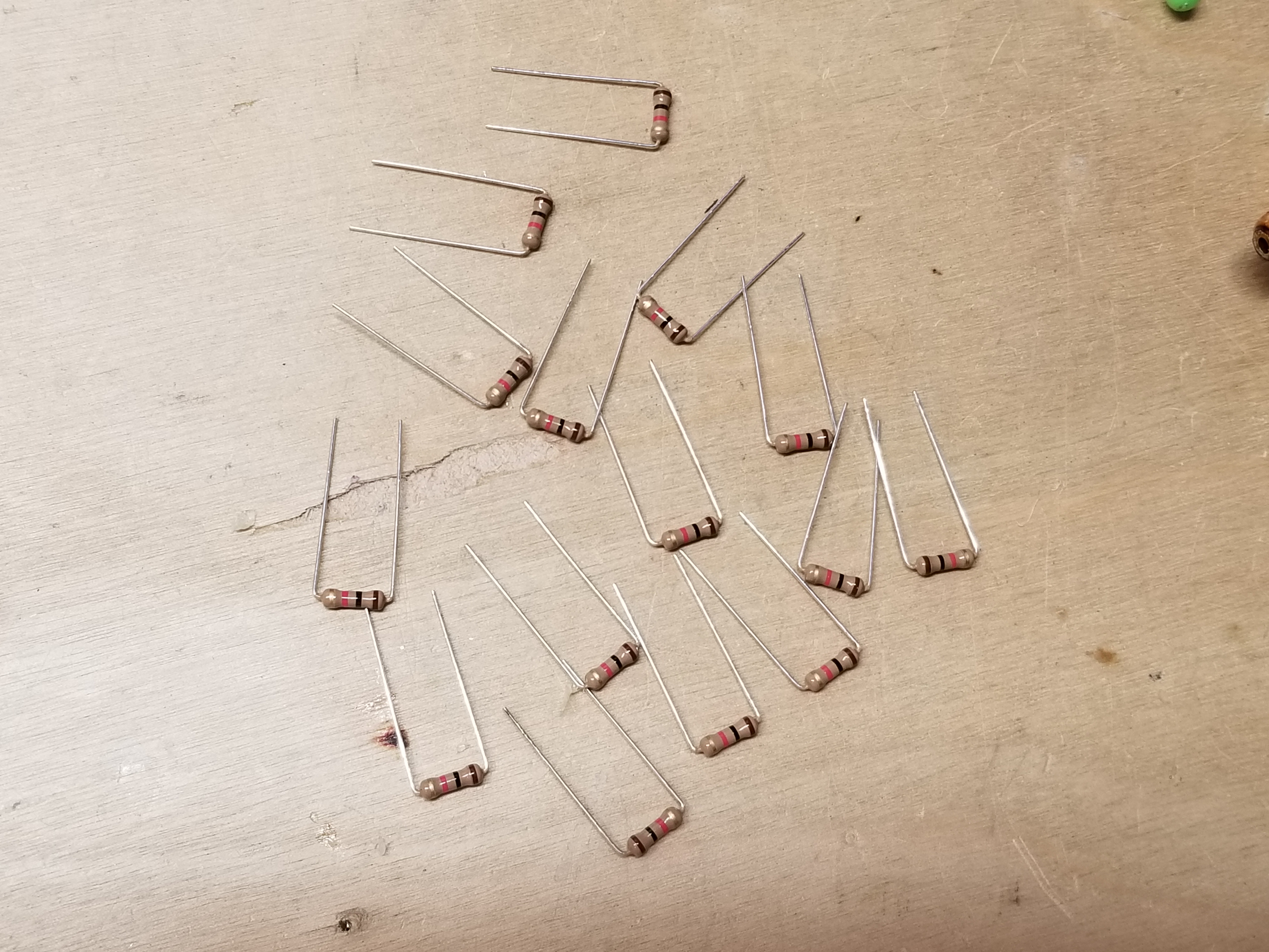
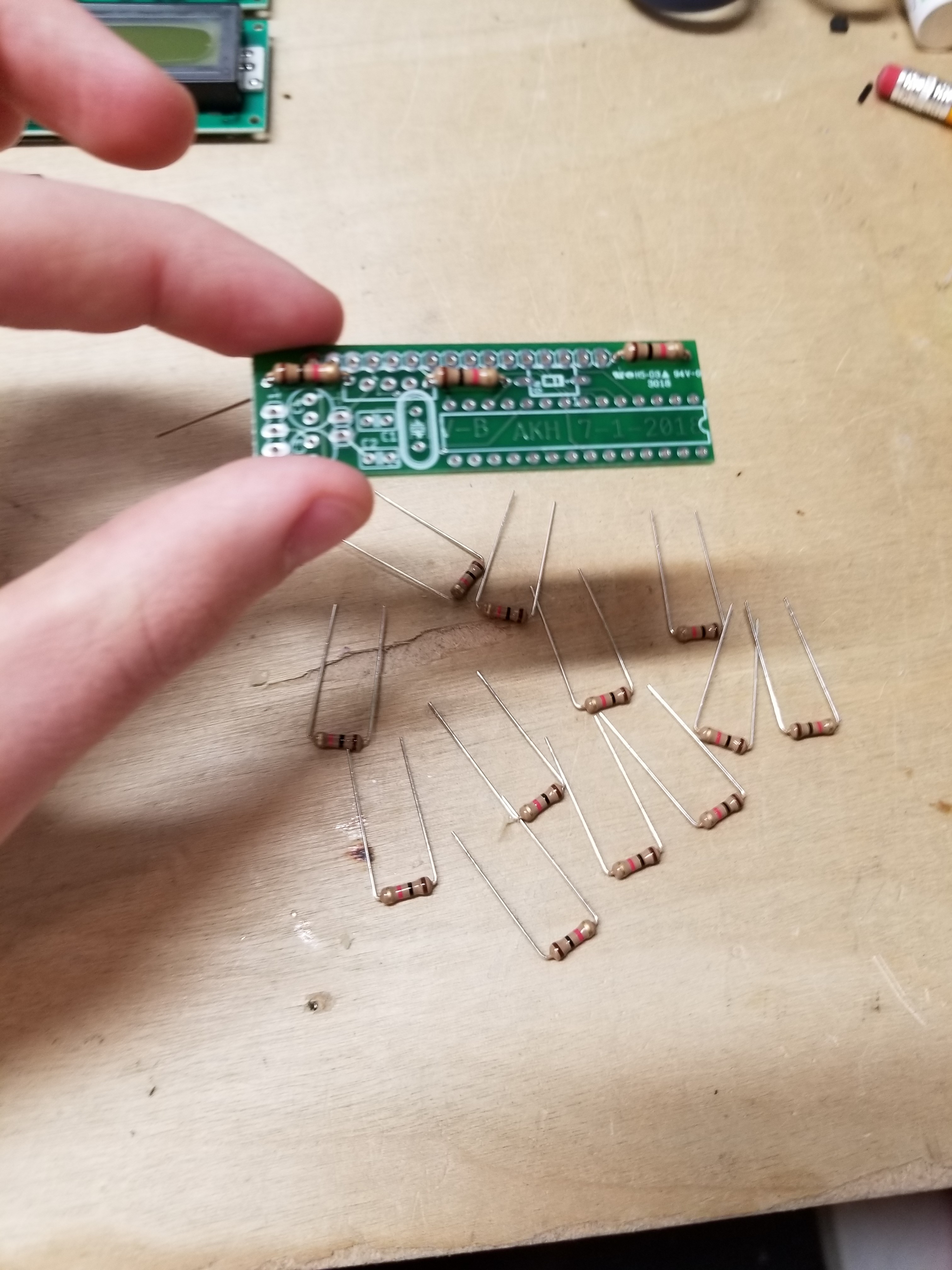
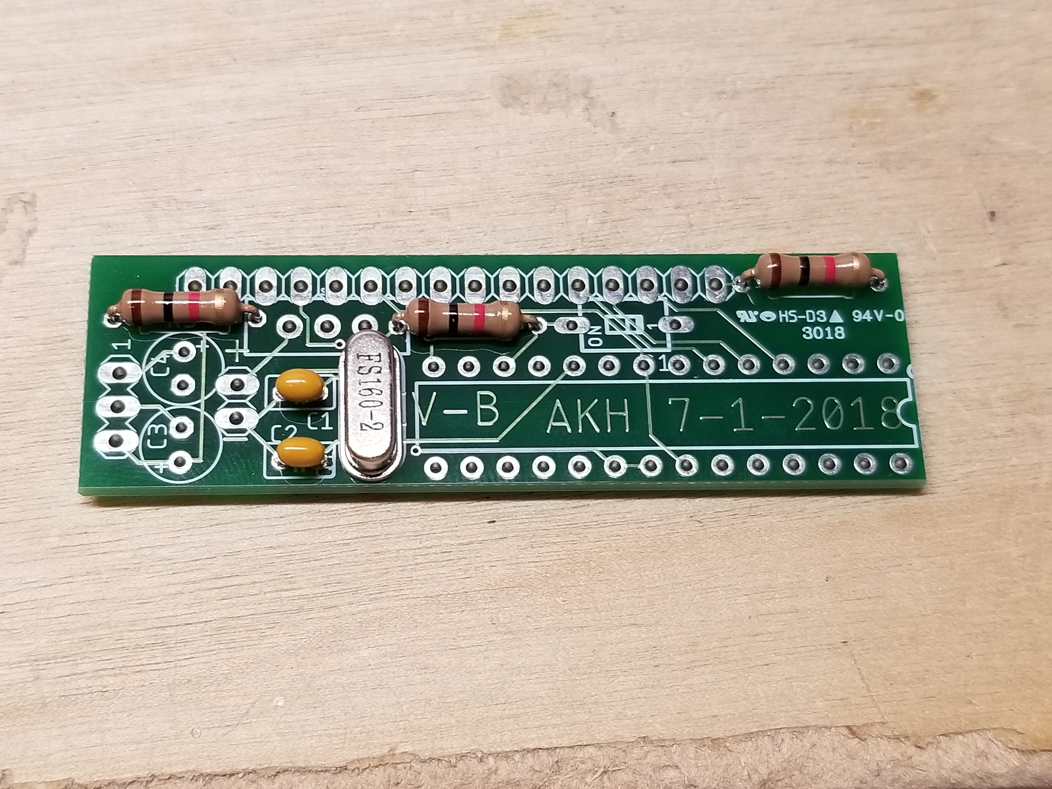
Next, I bend the resistors. I have to do this beforehand because I use the giant 1/2 watt resistors.
I populate the board...
...grab the crystal and its related caps...
...populate and solder them onto the board...
...grab the electrolytics...
...populate them...
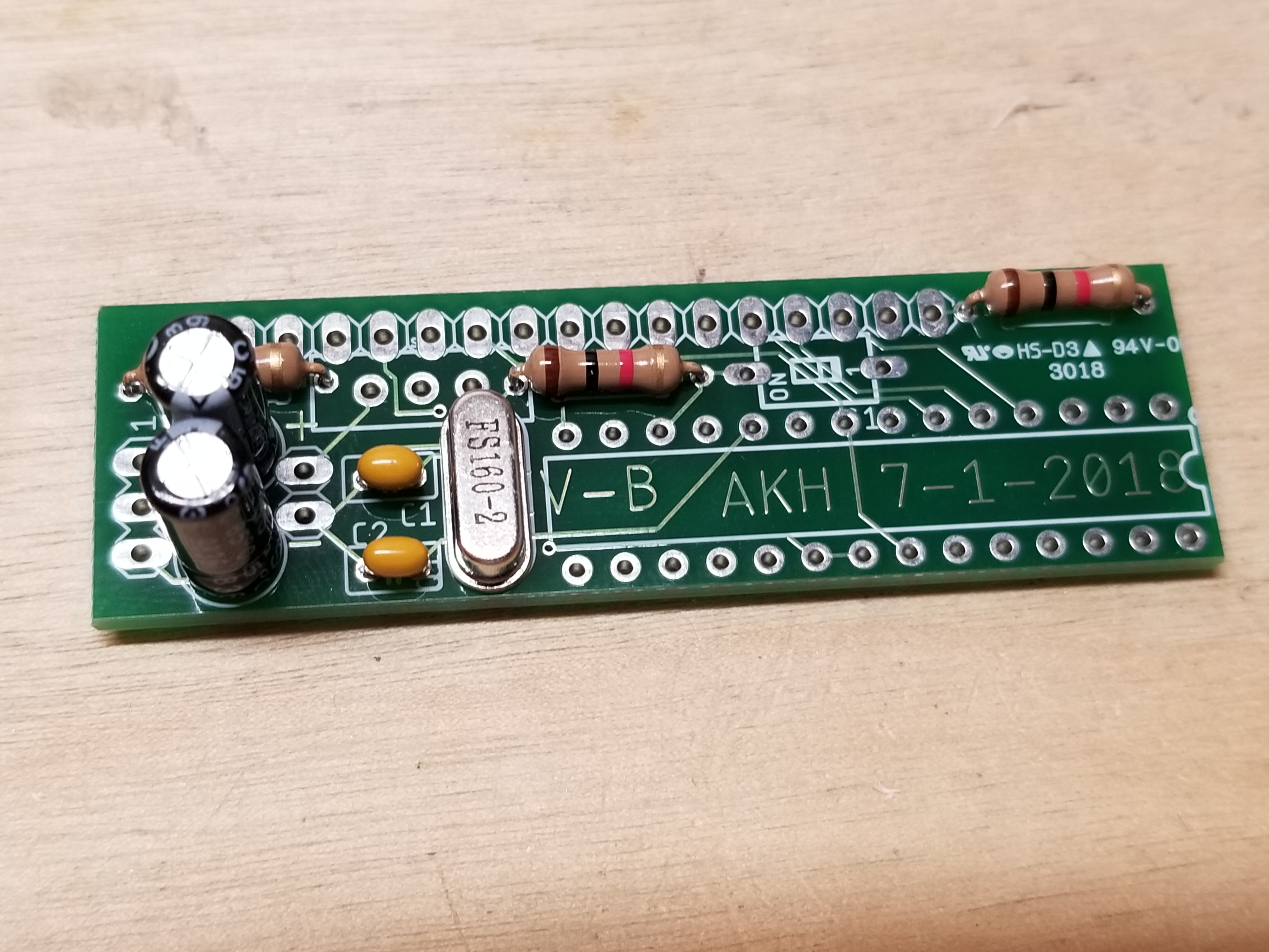
..add the regulator...
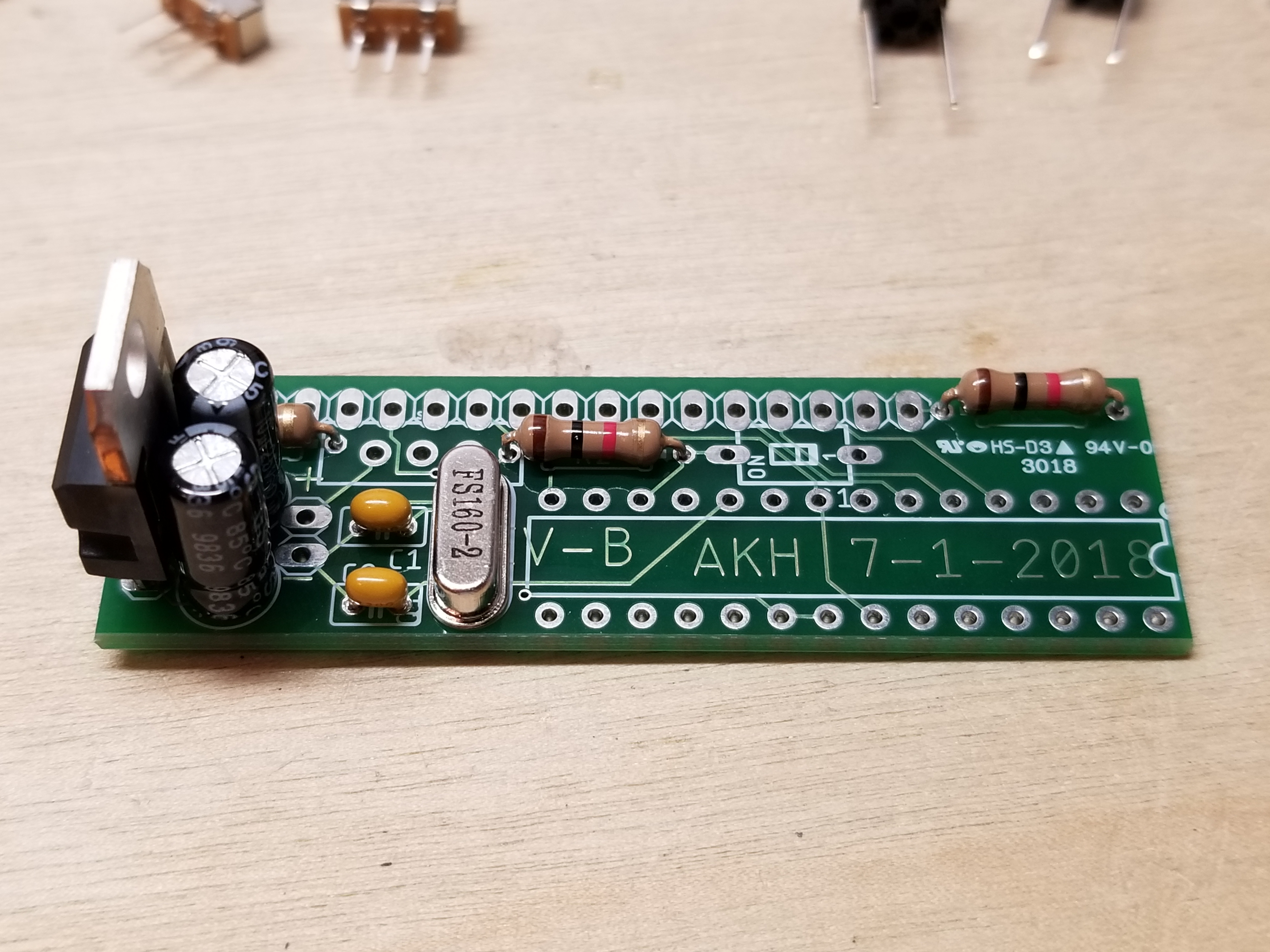
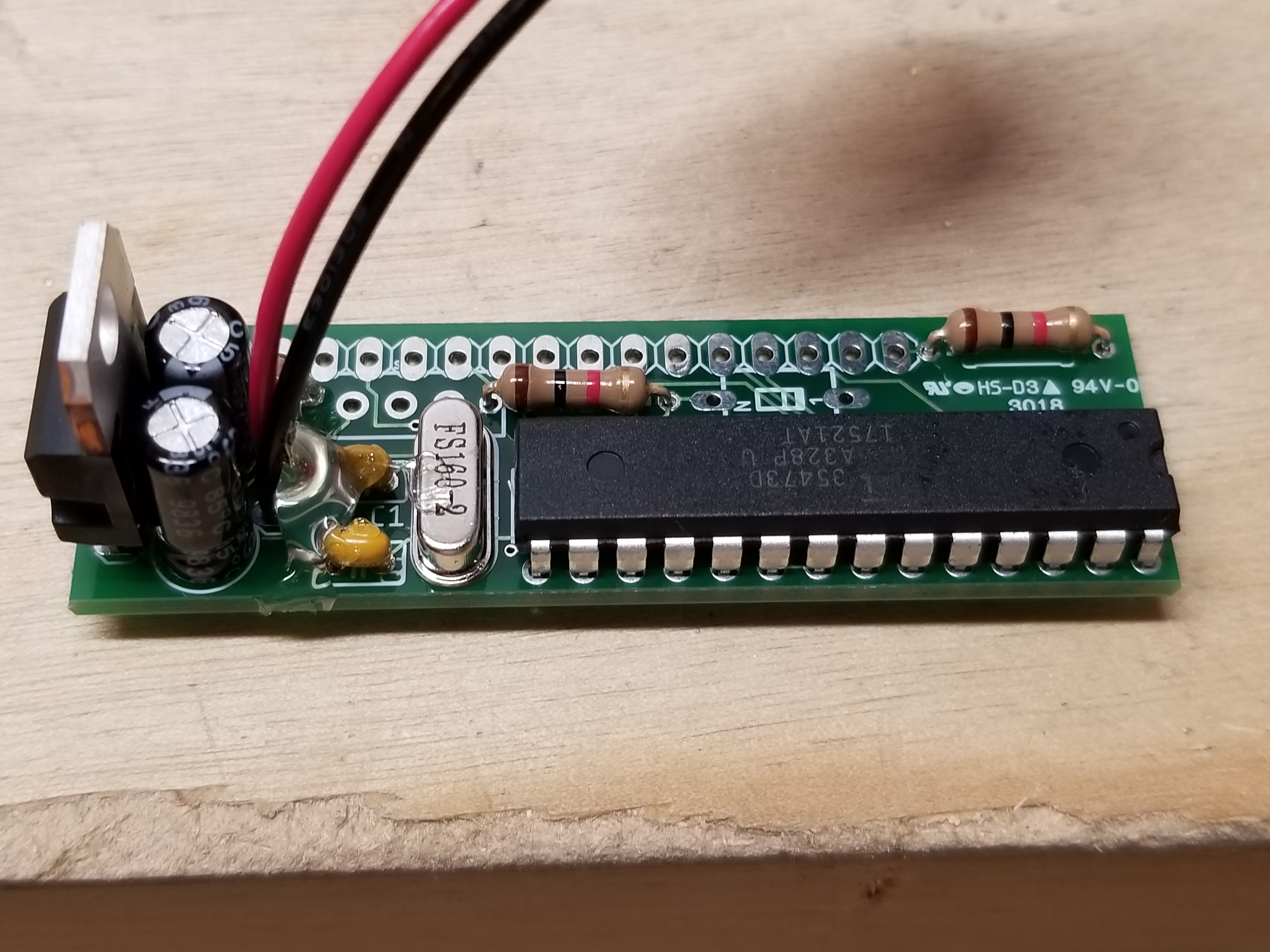
...and this is my progress thus far.
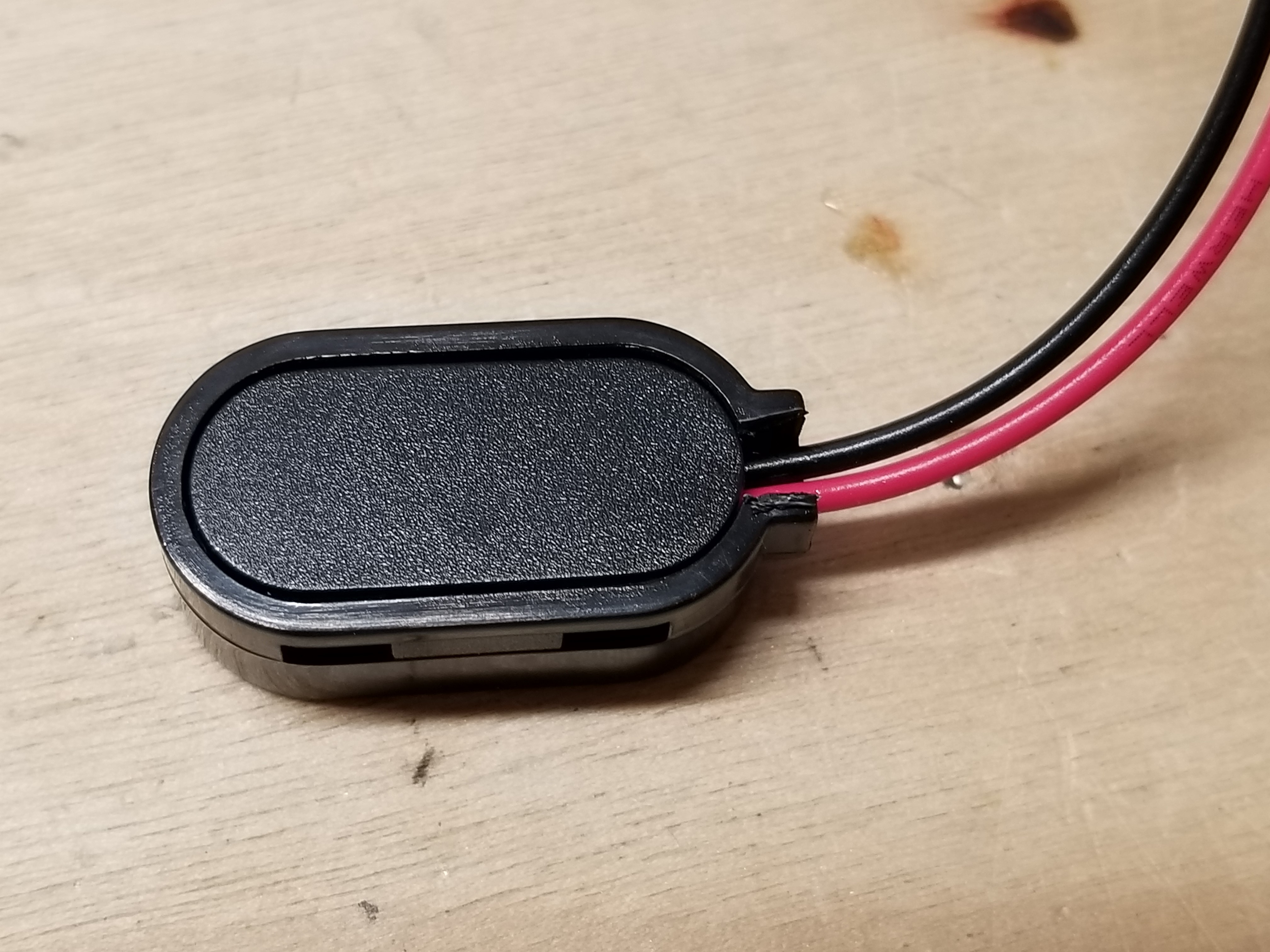
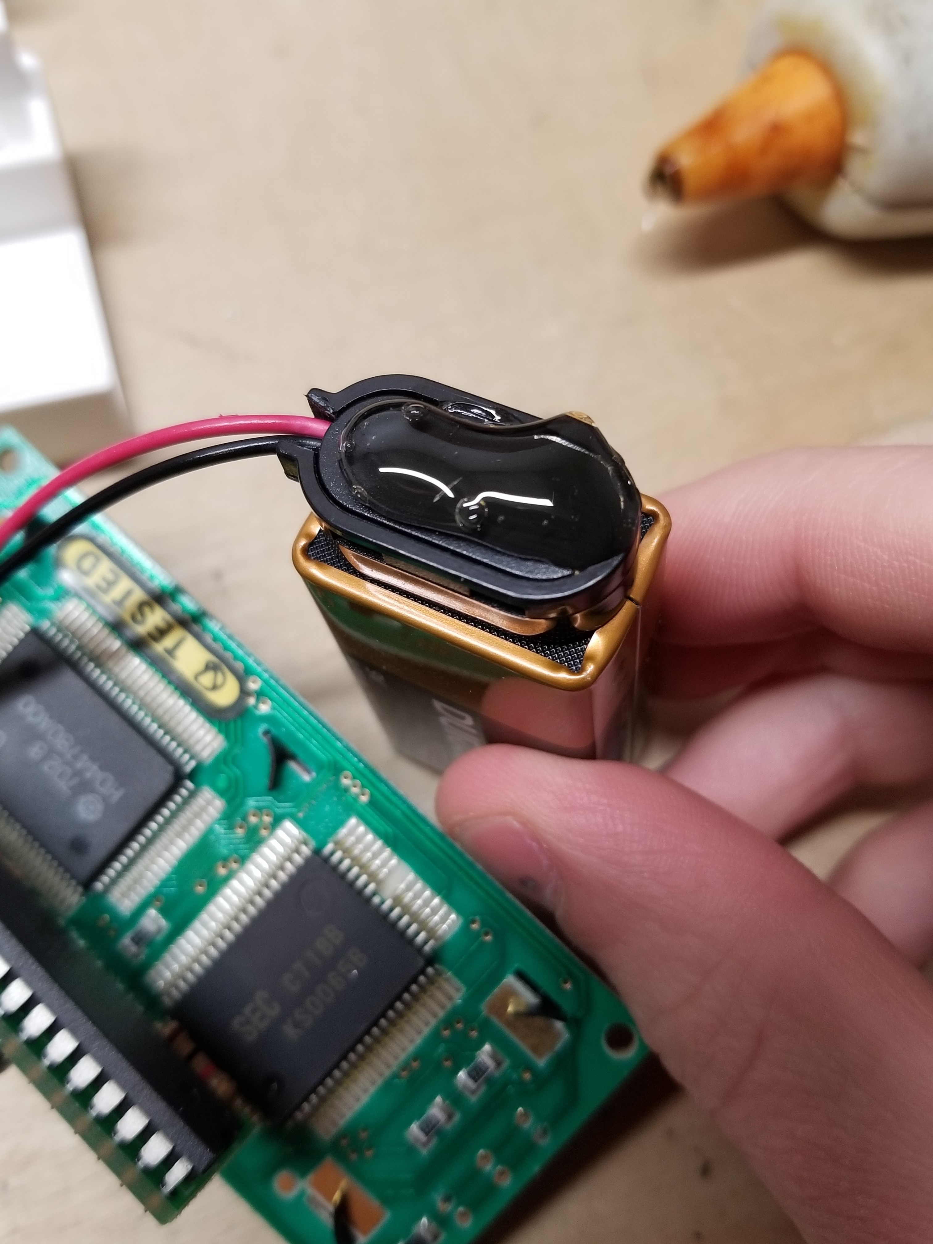
I modify the battery clips to allow for less space to be taken up by the wires.
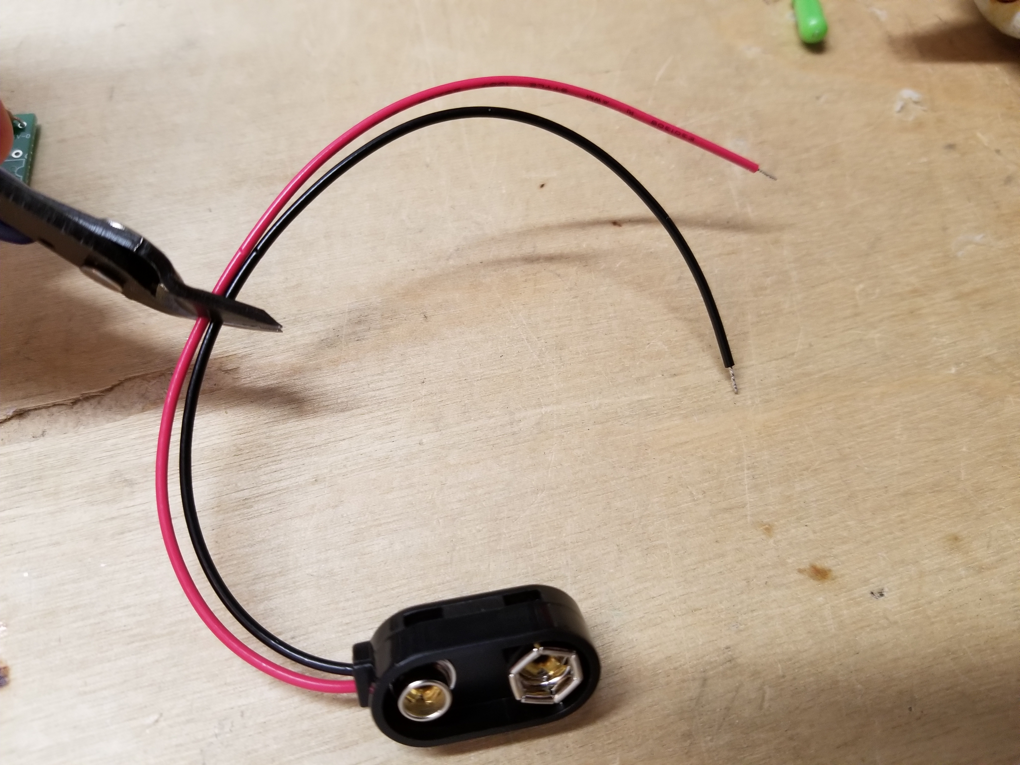
I shorten the leads...
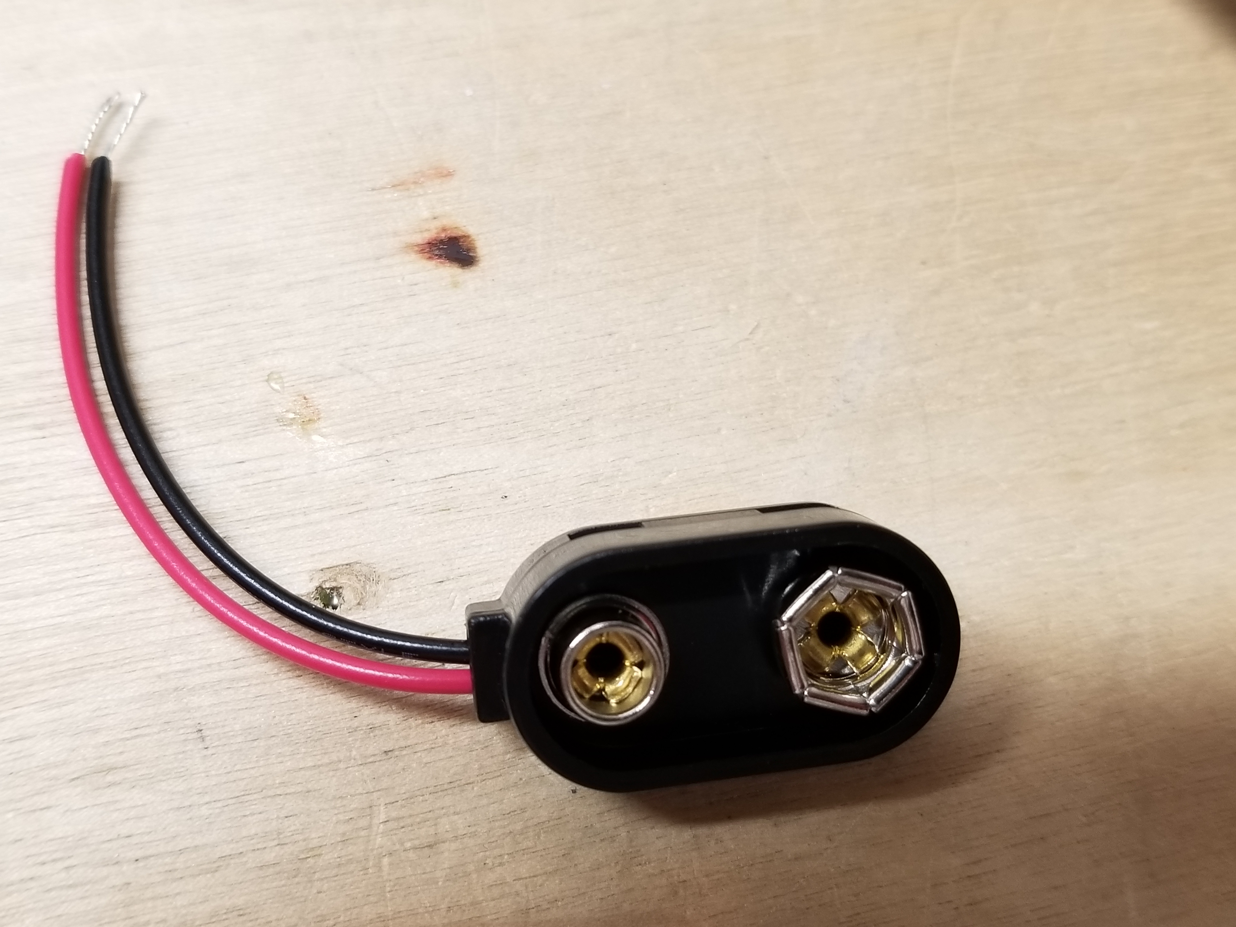
...flip it over...
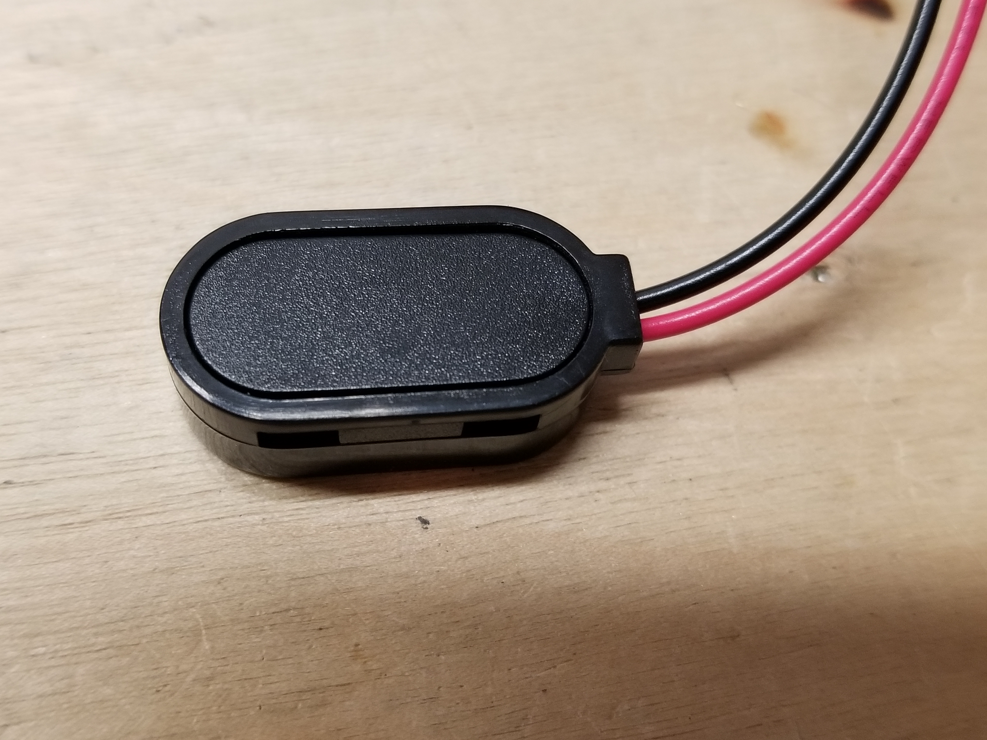
...cut away this part of the back...
...and here it is, finished.
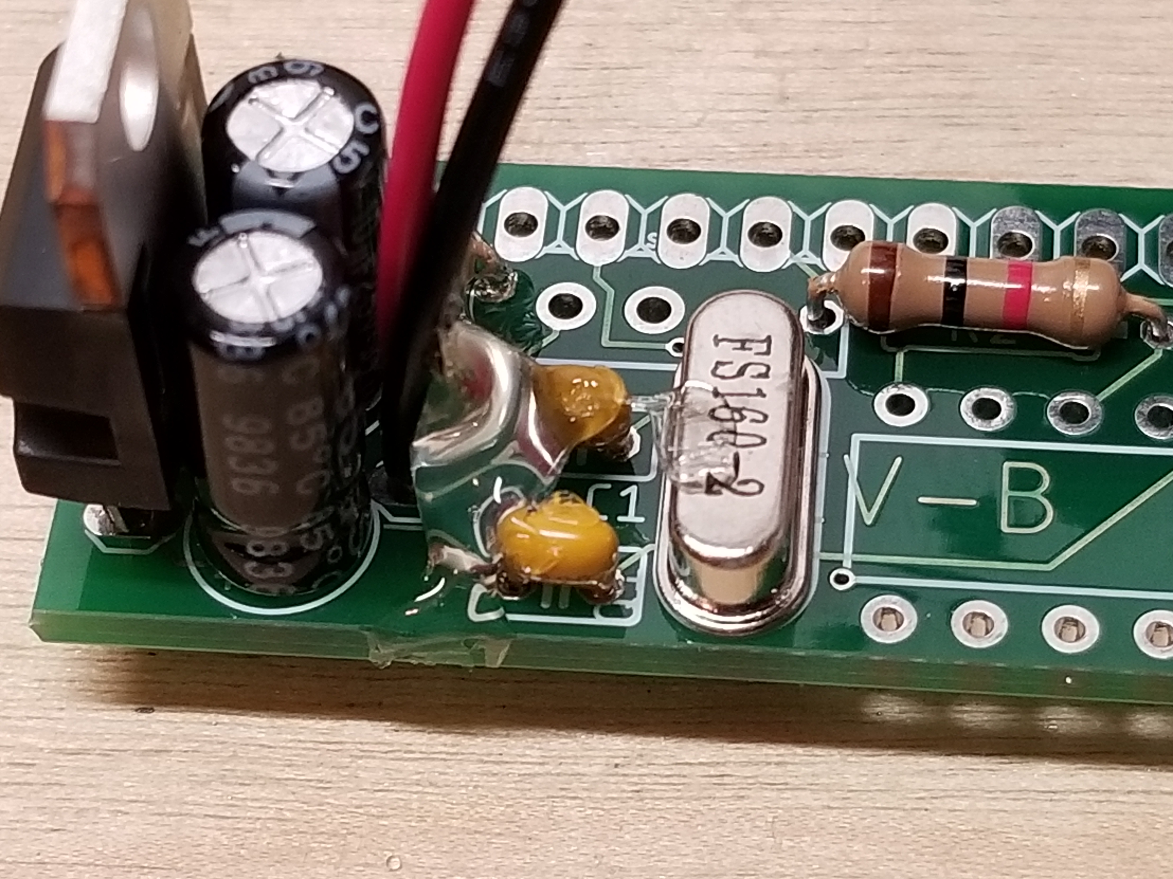
Next, I solder on the battery clip.
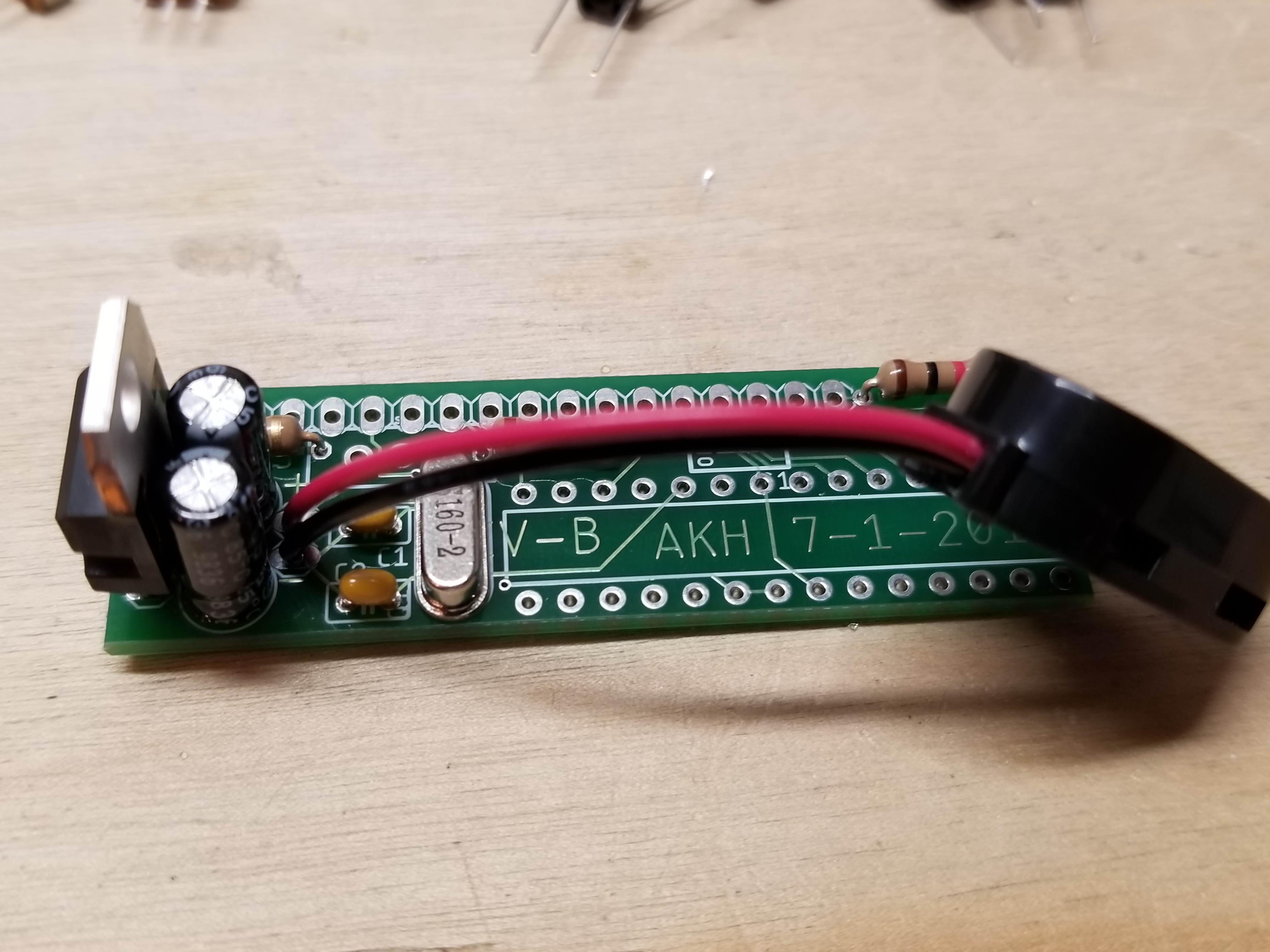
I always add hot glue to the base of free wires to keep them from breaking off.
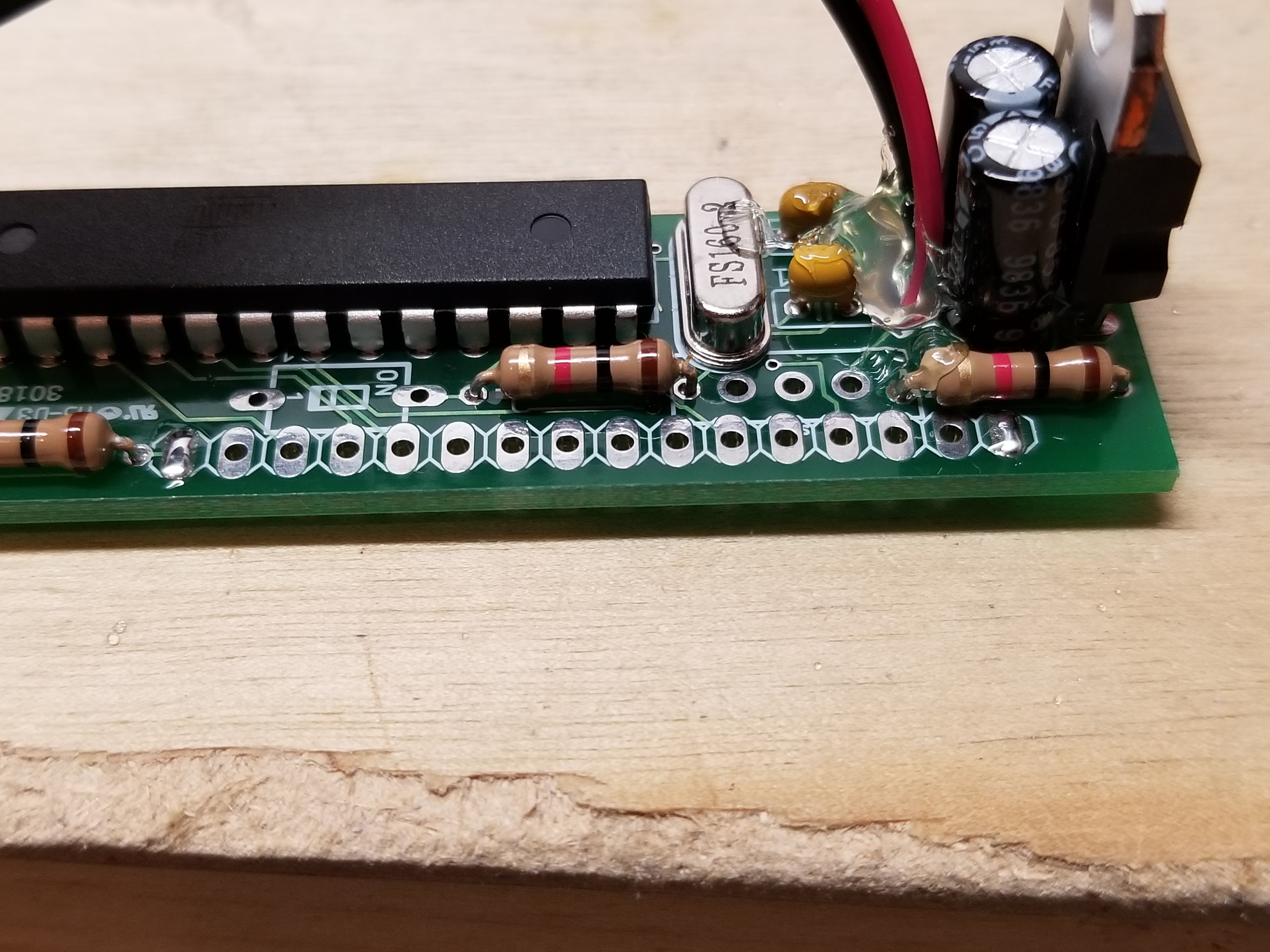
This is my progress thus far.
The most critical part: installing the Atmega. I turn down the heat on my iron so I won't fry it.
I've finsished the boards up to adding the display.
I then glob some solder on pins 16 and 1...

...cut the header down to 16 pins...
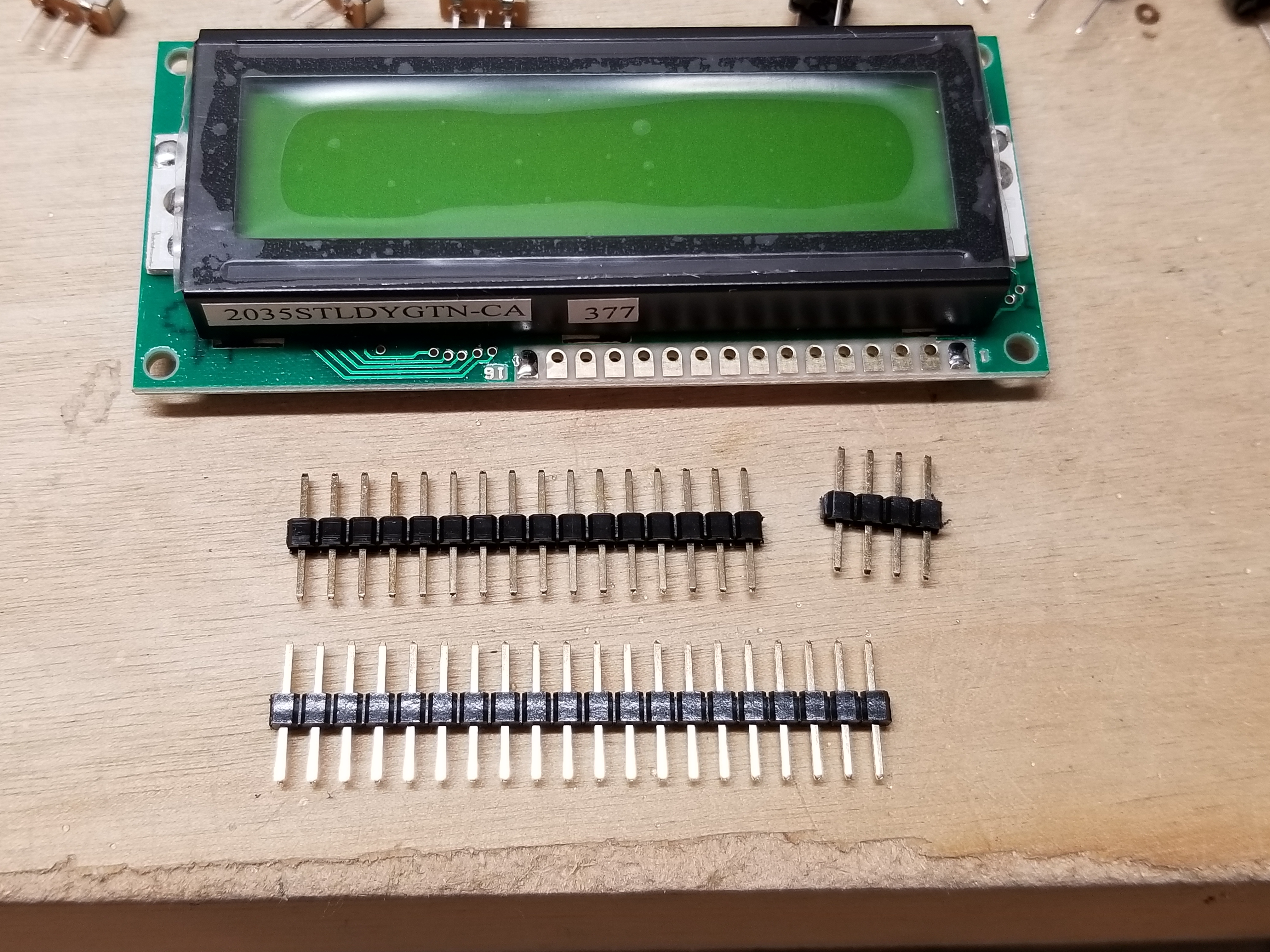
...melt the solder globs, and just barely push the pins in.
Next, I solder the rest of the pins.
I put some solder on pins 16 and 1 of the header on the board...
...and gently melt the solder and push the board on, like with the LCD.
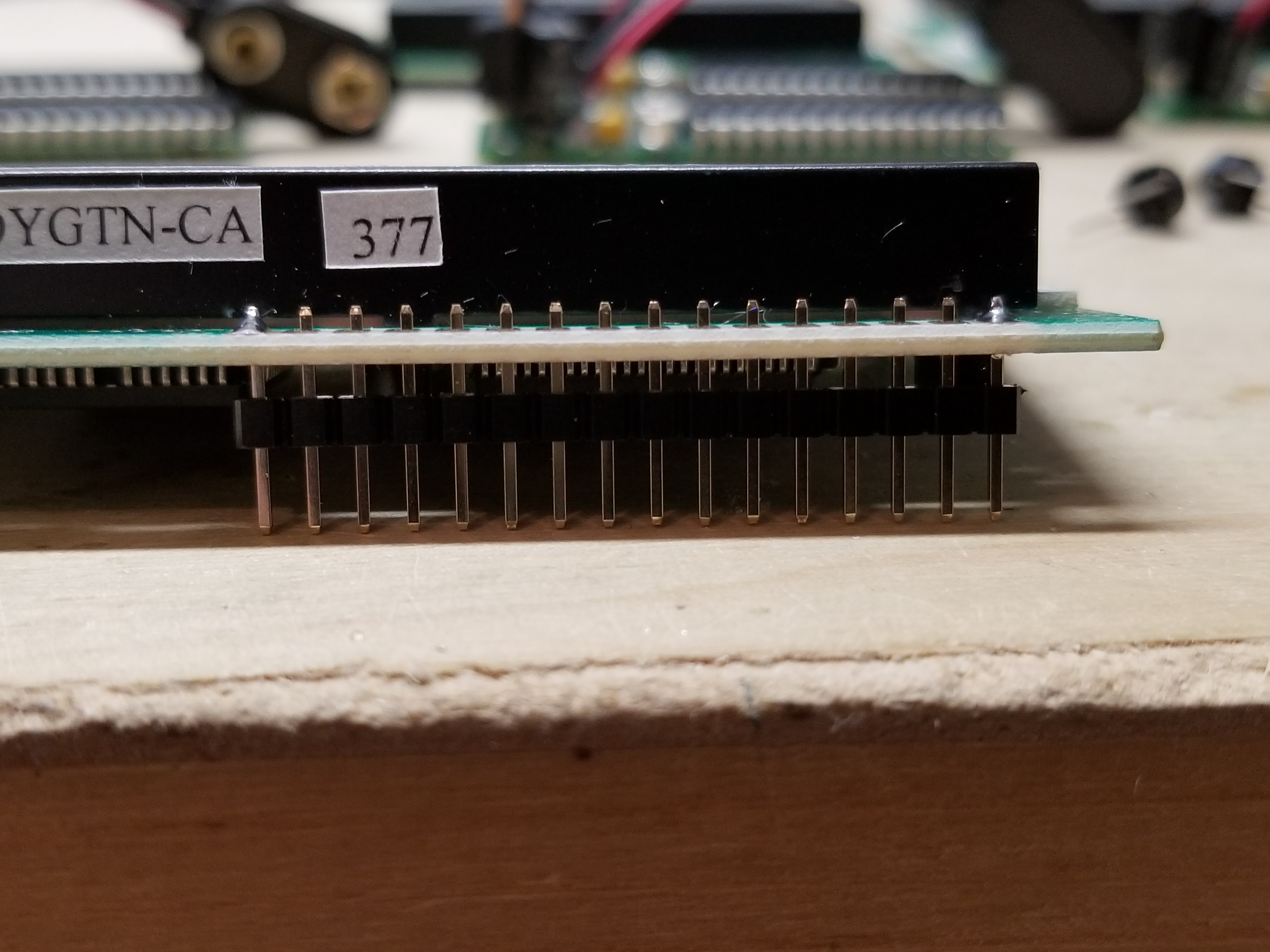
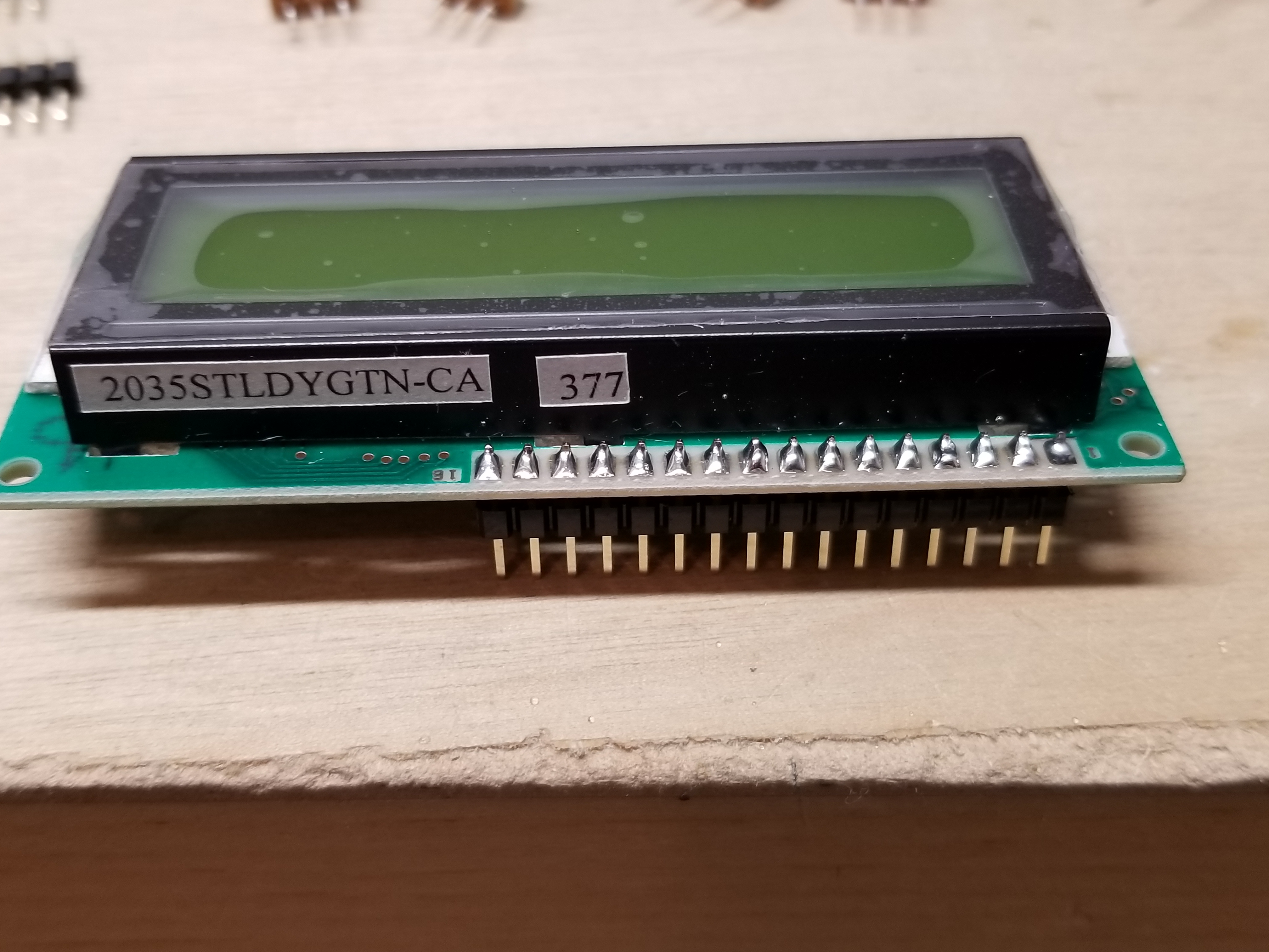
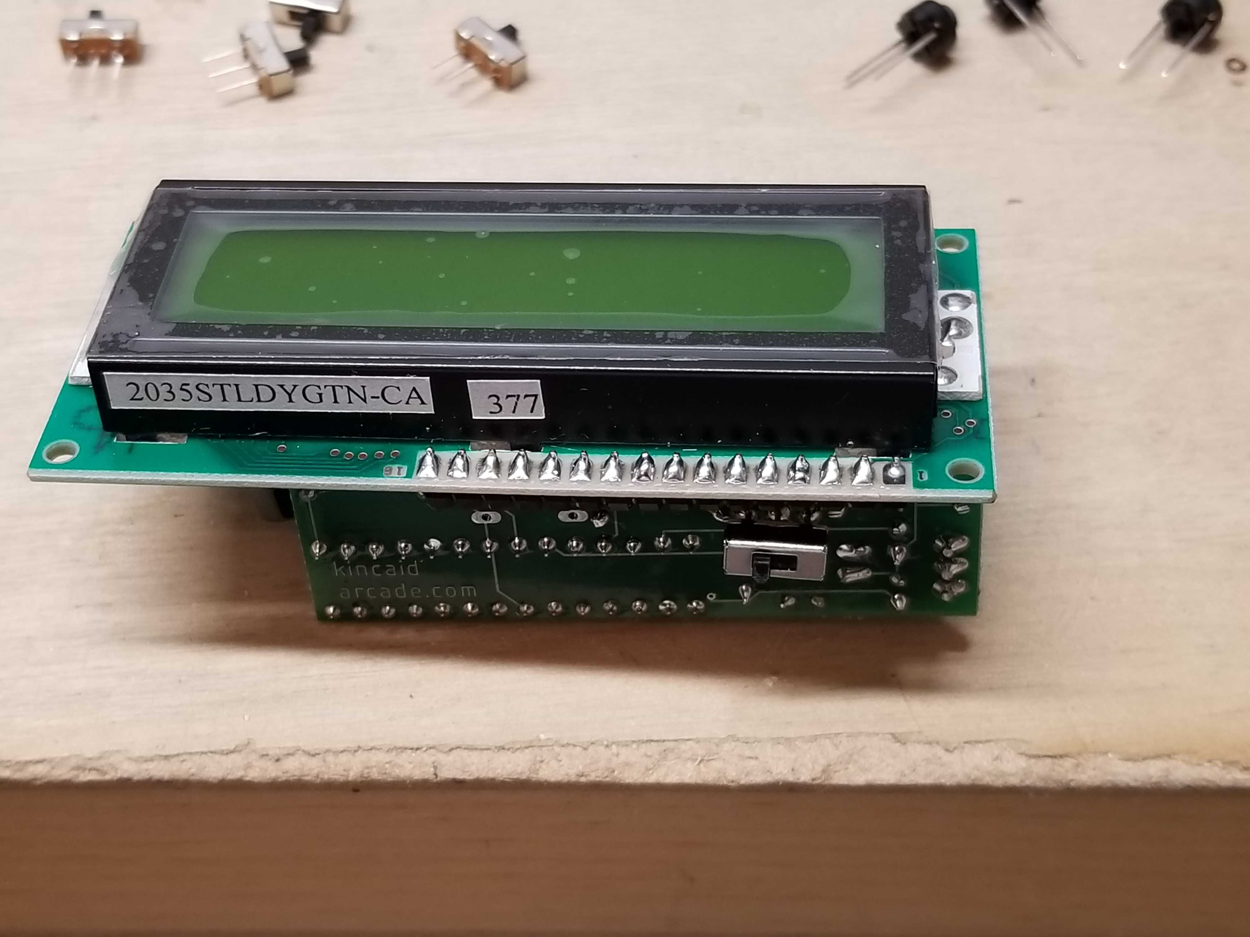
There should be space between the LCD, header, and board.
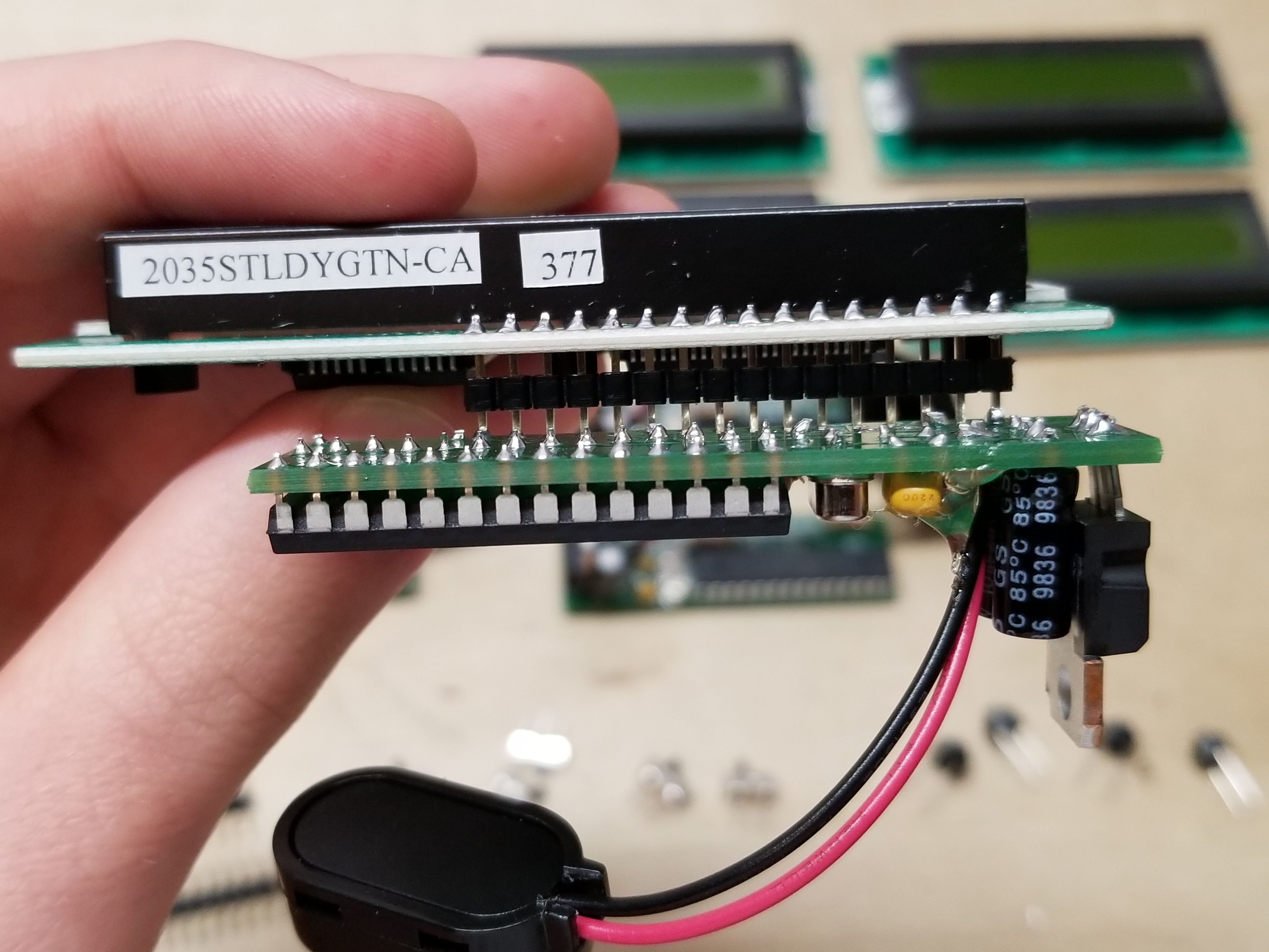
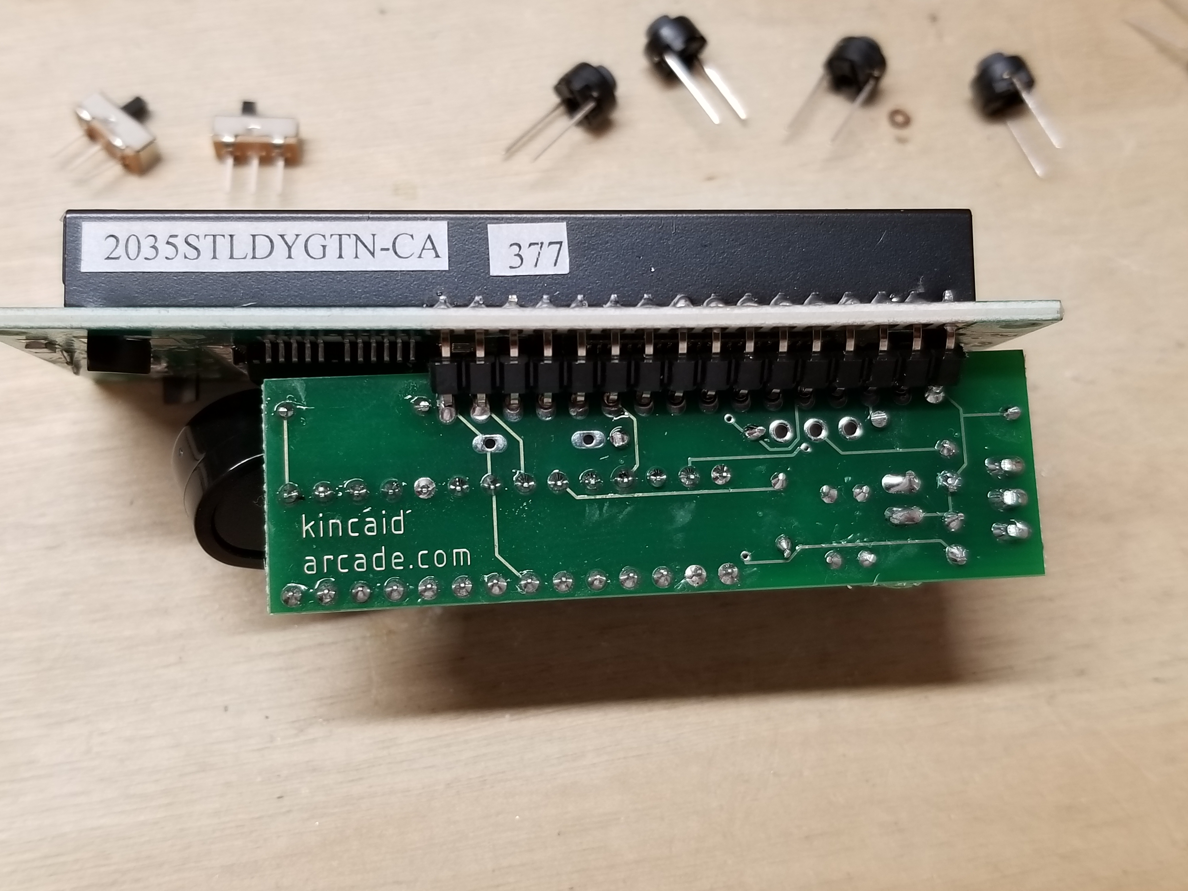
After they've been soldered up, they look like this.
Those two black tabs at the bottom need to be pushed back a bit for the next step.
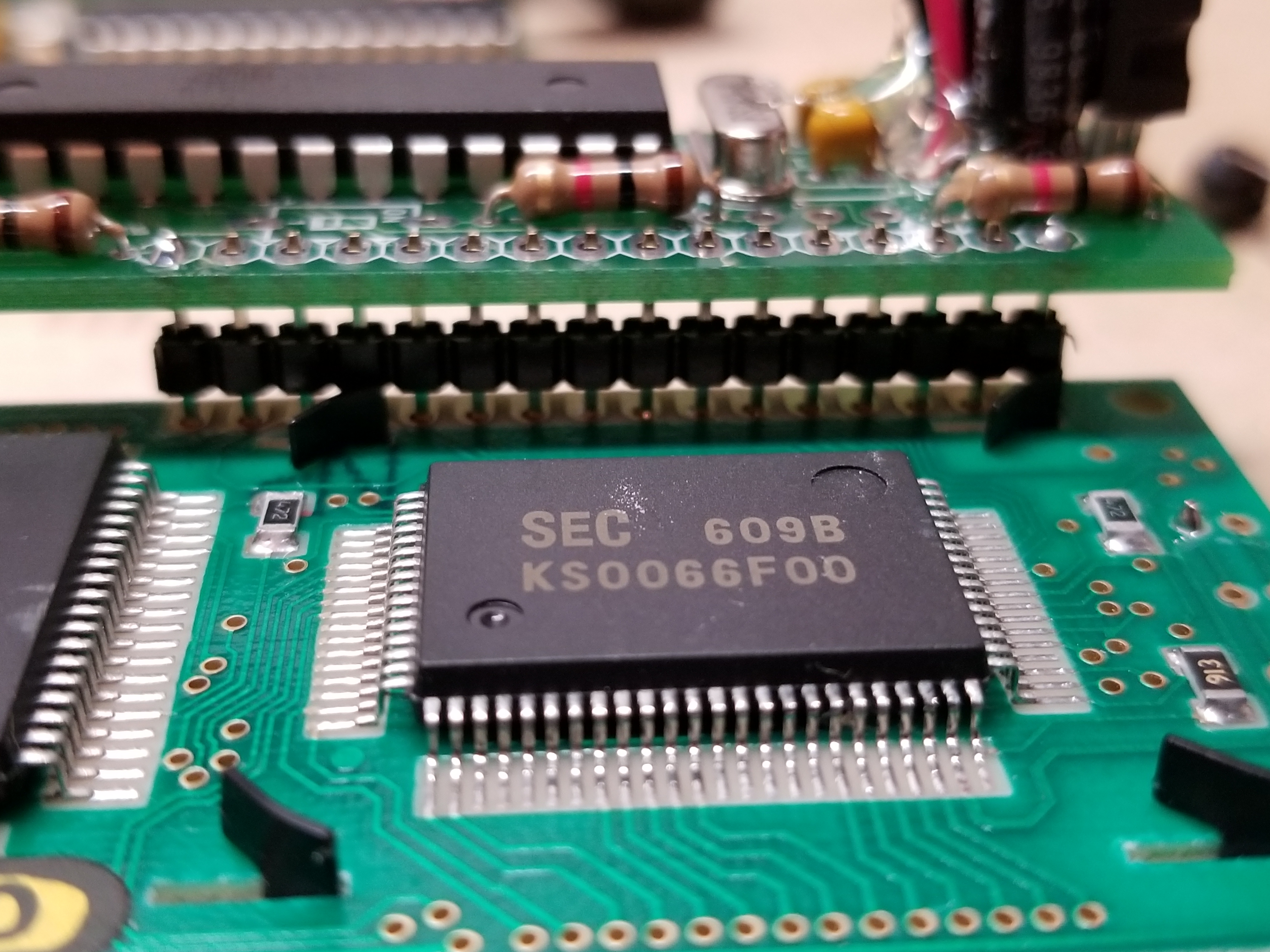
Next, I have to bend the headers to get the board perpendicular to the LCD.
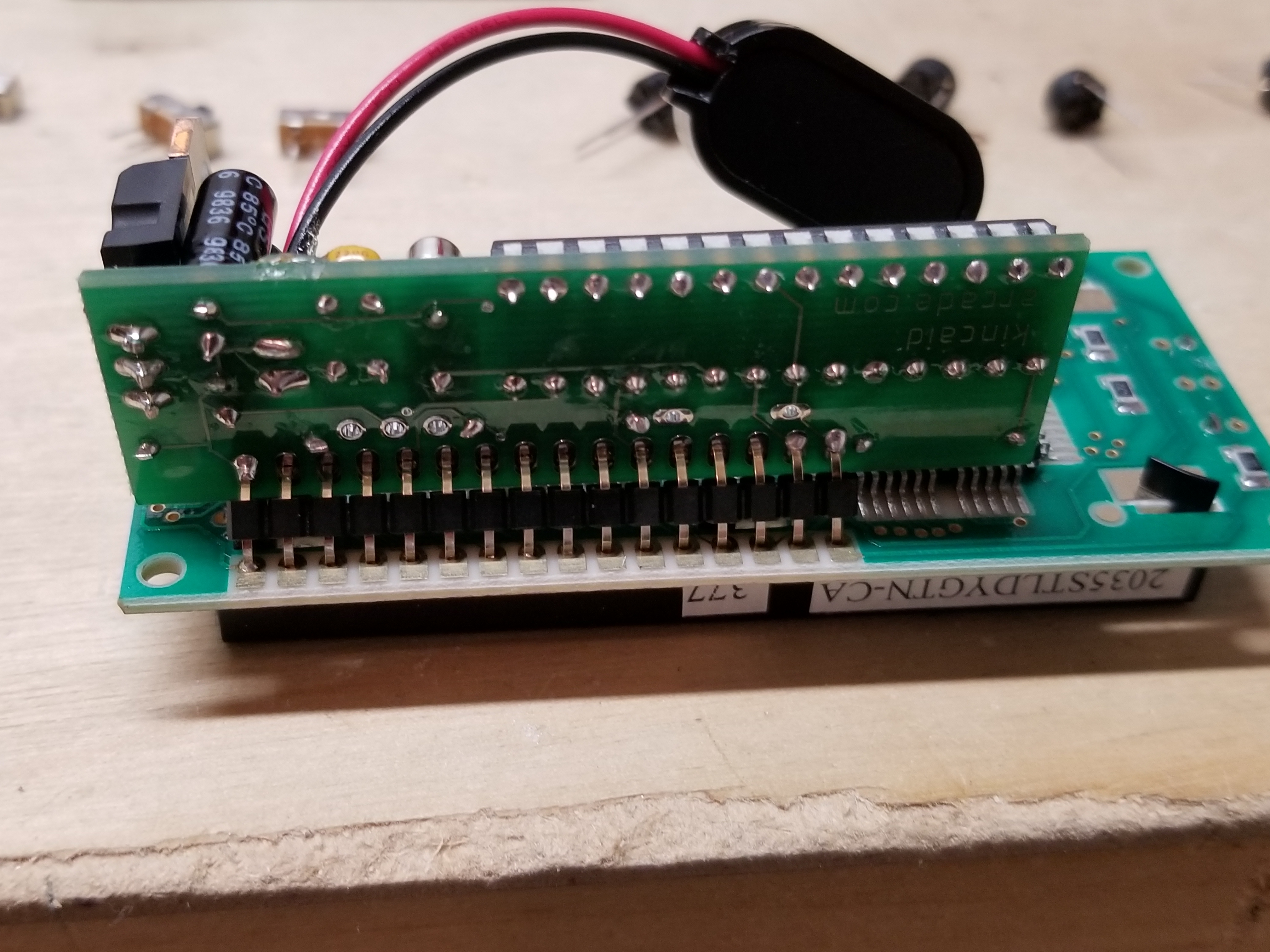
It doesn't have to be a perfect right angle.
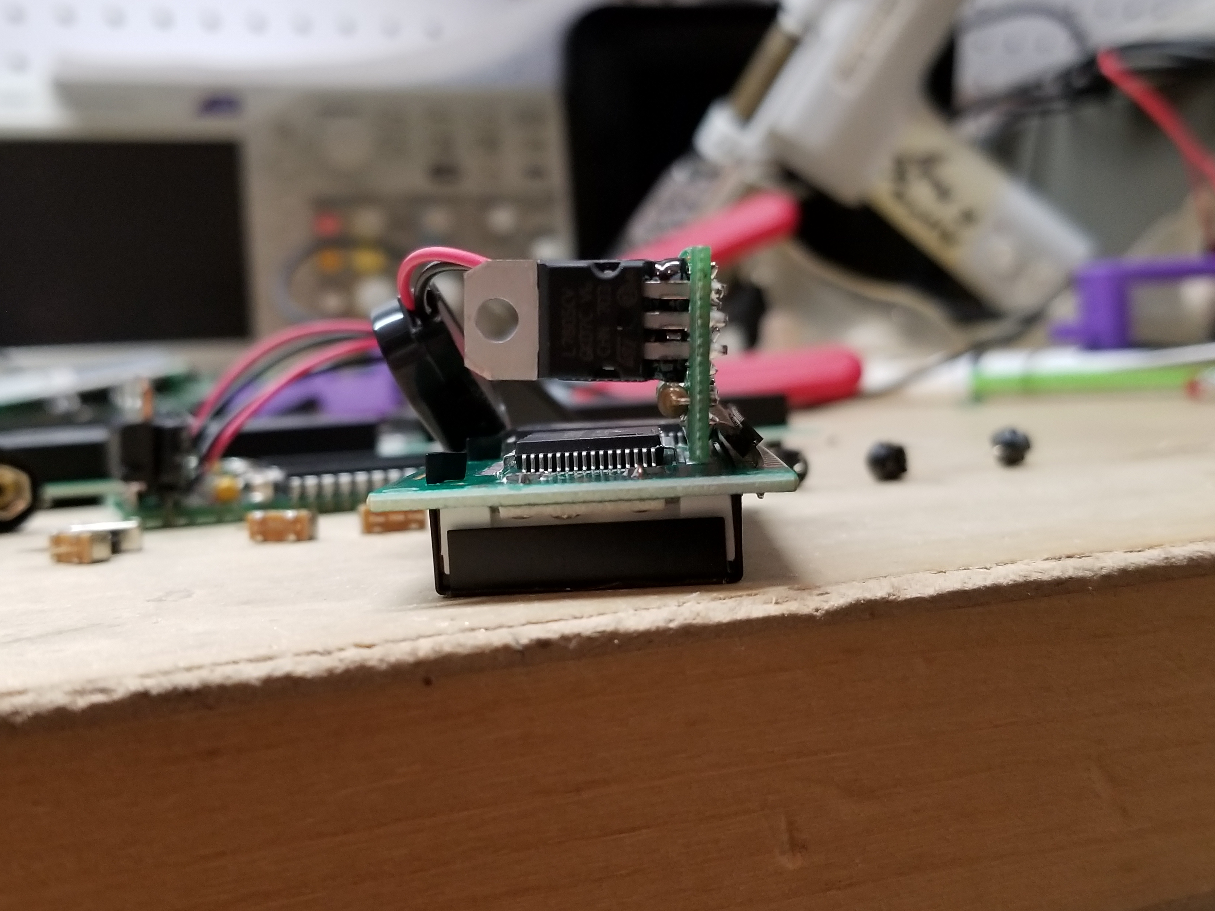
The board will not be even to the display, either.
Next, I glob solder on one of the holes for the switch...
...melt the solder on that hole, and just barely push the switch in.
It should just barely stick out beyond the front of the display.
I do the same for the button.
The bottom of the button should stick out beyond the front of the display.
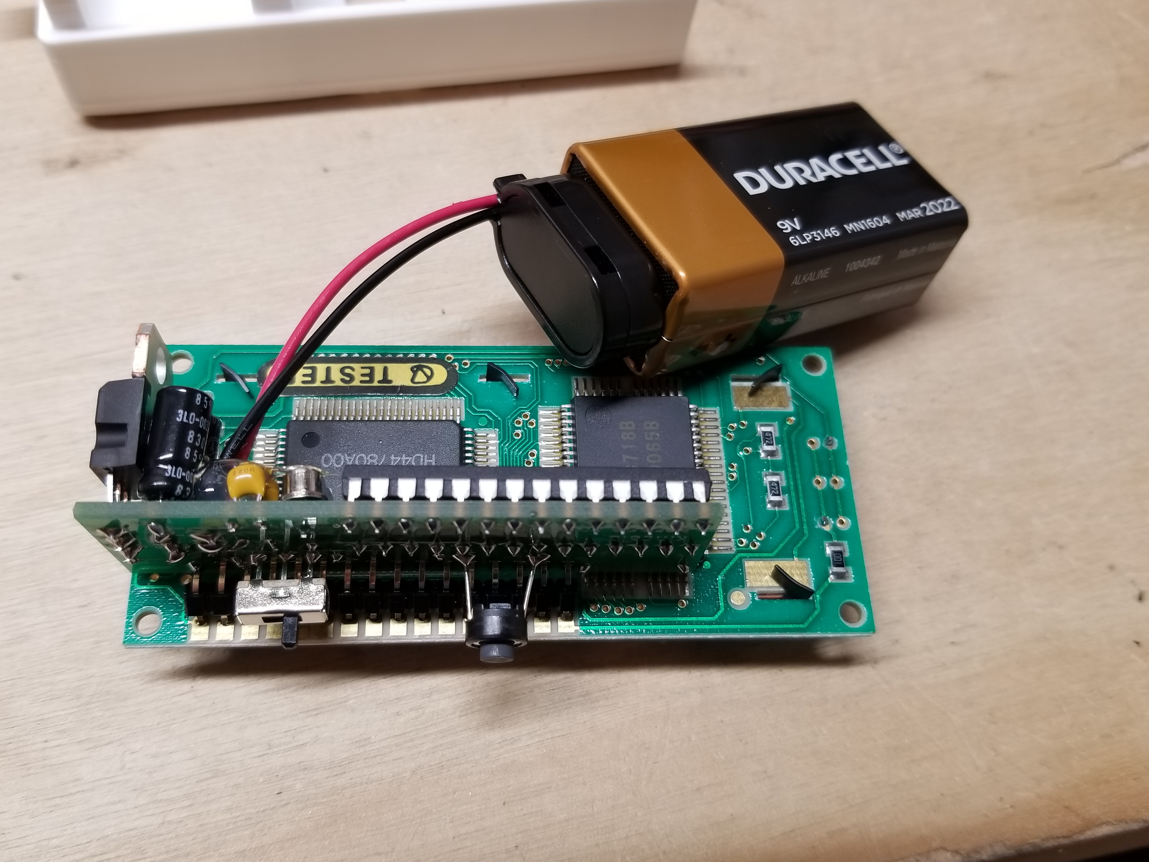
I have now finished all of the soldering. Now, I insert the battery.
I switch it on...
If it works, I write the serial #.
And here it is, with the other four.

How I mount it into the case
With the difficult part done, the last thing I do is put the boards and LCDs into cases. This adds some function, rigitity, and it just plain looks nice. Then, I give them away to family and friends.
I start by bending the wire on the battery clip. That is why I cut away that part of the clip.
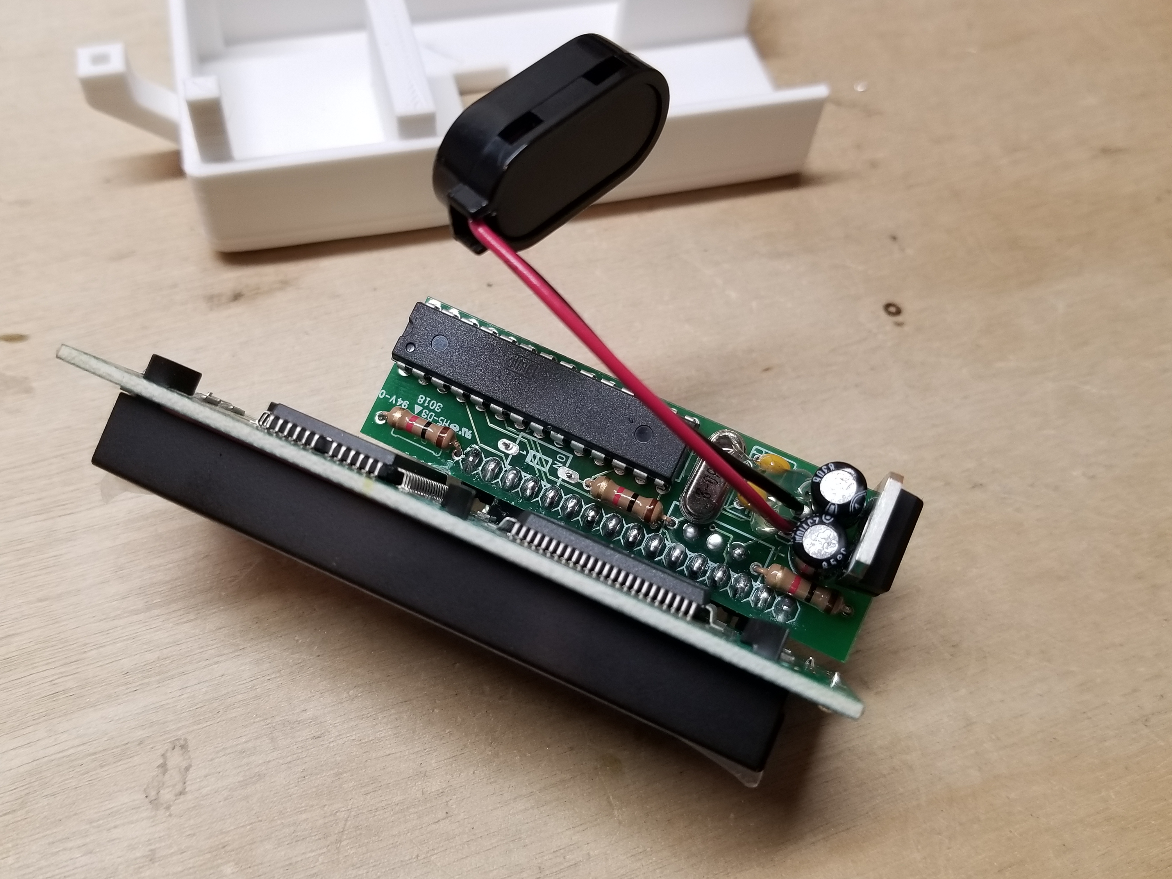
Then, I insert the battery because it helps with the next steps.
I add hot glue to the top of the battery clip,...
...and I shove it into the wall on the case. This will allow the battery to be inserted easily.
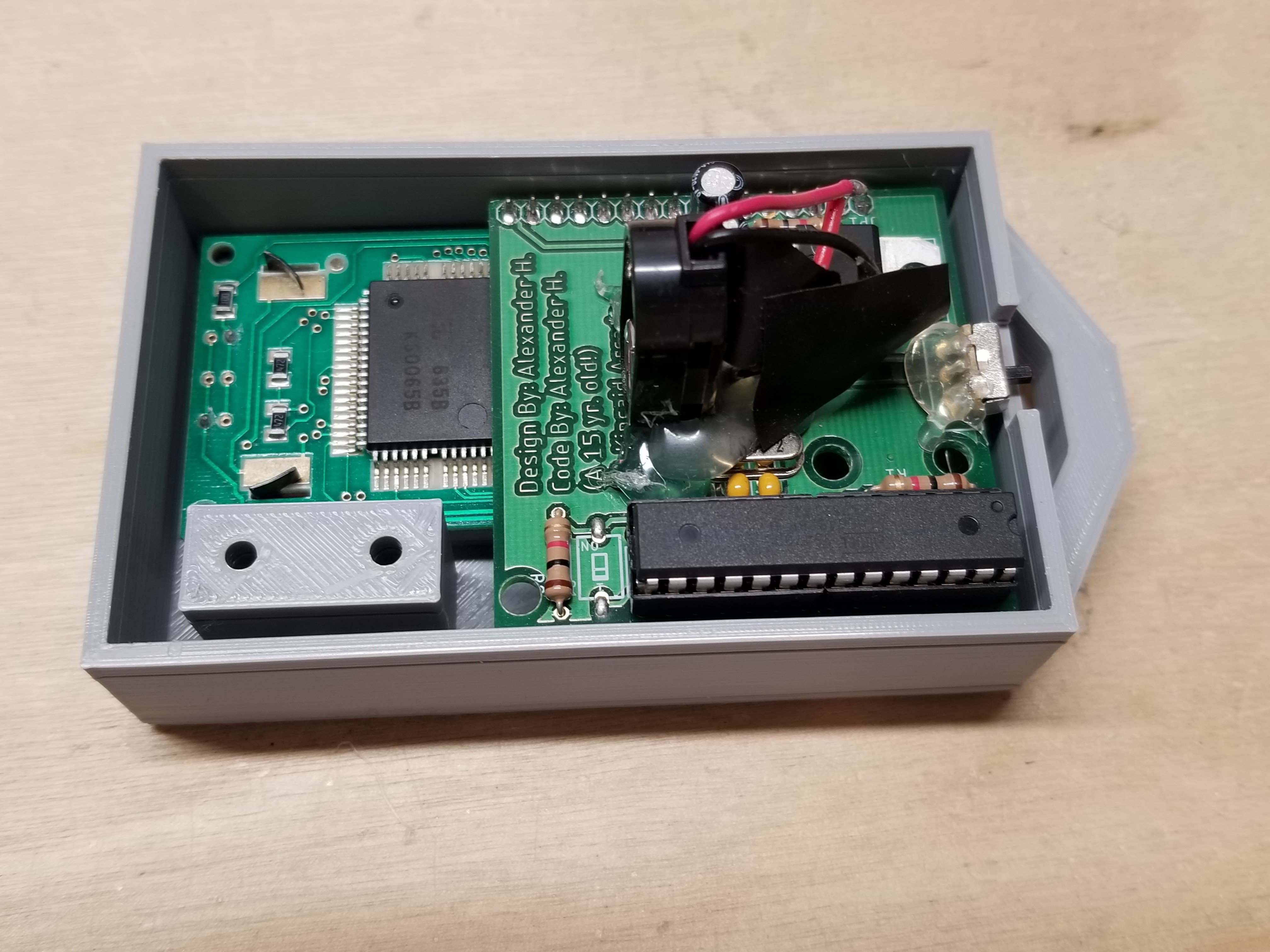
The next steps are always easier when I place the board and display in the top half.
I add hot glue in those three corners for added stability. It would just be a press-fit case, otherwise.
Next, I push the bottom half of the case on. I have to do it fast, or the hot glue will harden.

Lastly, I add a little '+' next to the battery hole to indicate which way the battery should go...
...and it's finished!
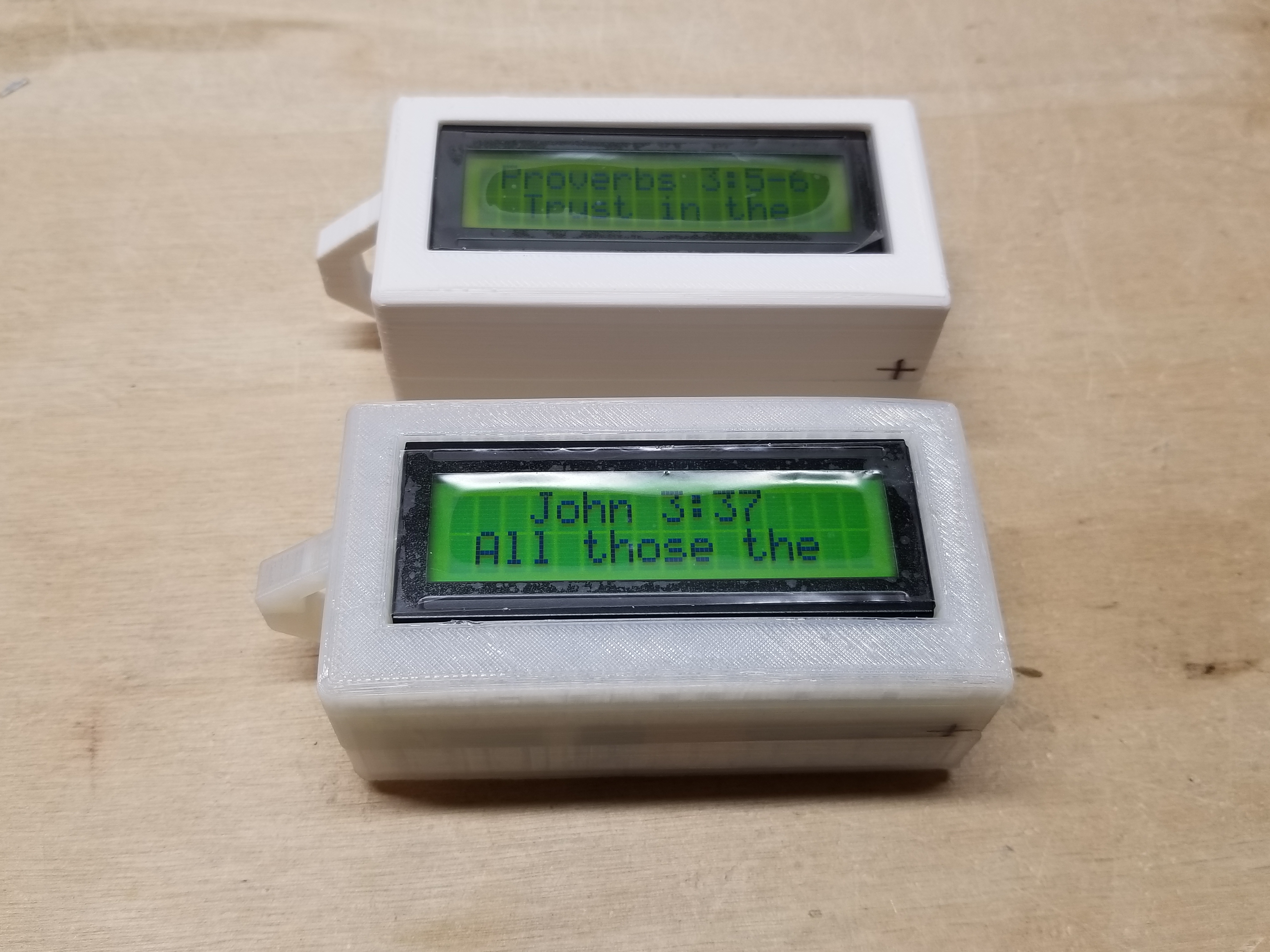
Here are serial numbers 22 and 23, completed.
Number 22 has the translucent case, and number 23 has the white case.
I also shot a video of numbers 22 and 23 in action:
This page was published sometime in December of 2018
This page was last updated 1/5/2022
Spelling, grammar, and readability corrections.