Fixing Atari's QWAK! (1974)
(This first section was written by me more than two years ago. I am leaving it unchanged so that you can see the difference between my writing style as a 14-year-old, and what I can now do as a 17-year-old. If you want to skip to where I am actually able to fix it, click here.)
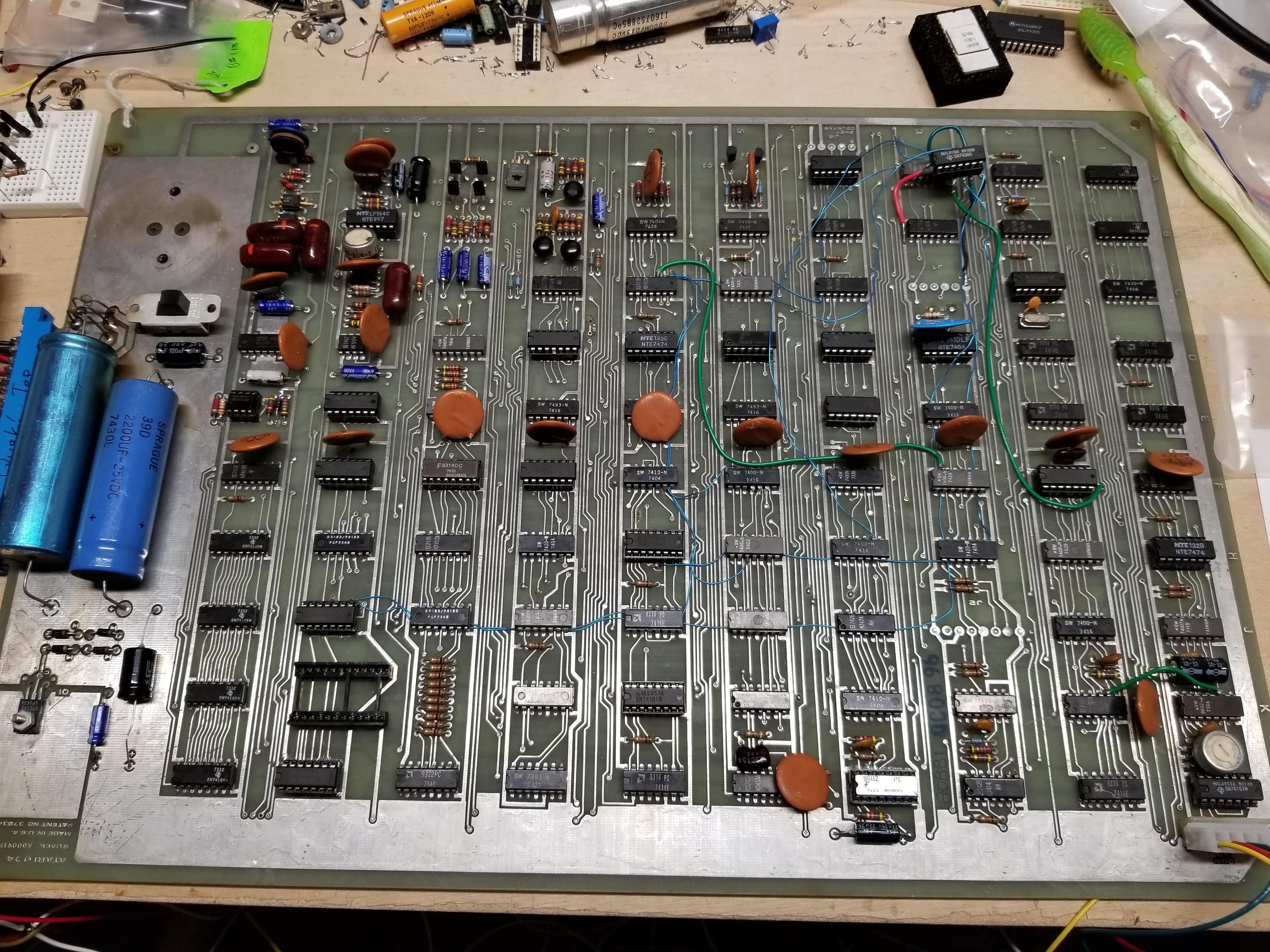
Atari's QWAK! is the third arcade PCB I bought.
I didn't let my current inability to fix the Olympic Tennis boards prevent me from buying more boards.
I bought this board from the guys at QuarterArcade, with the intention of dumping the ROM, to make it publicly available.
I wanted to dump the ROM so badly, because nobody on the Vintage Arcade Preservation Society's website had marked theirs as working.
Here is the circuit board. This picture is from the Ebay listing for the item I bought.
Source: QuarterArcade
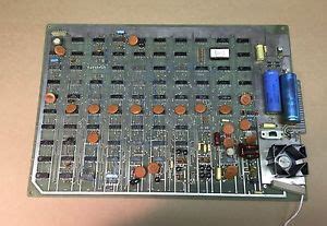
Somehow, the pic from the Ebay listing is still on the internet. Do a quick search:Atari QWAK! pcb.
Oh, wait. I put it on the internet. *FACEPALM*
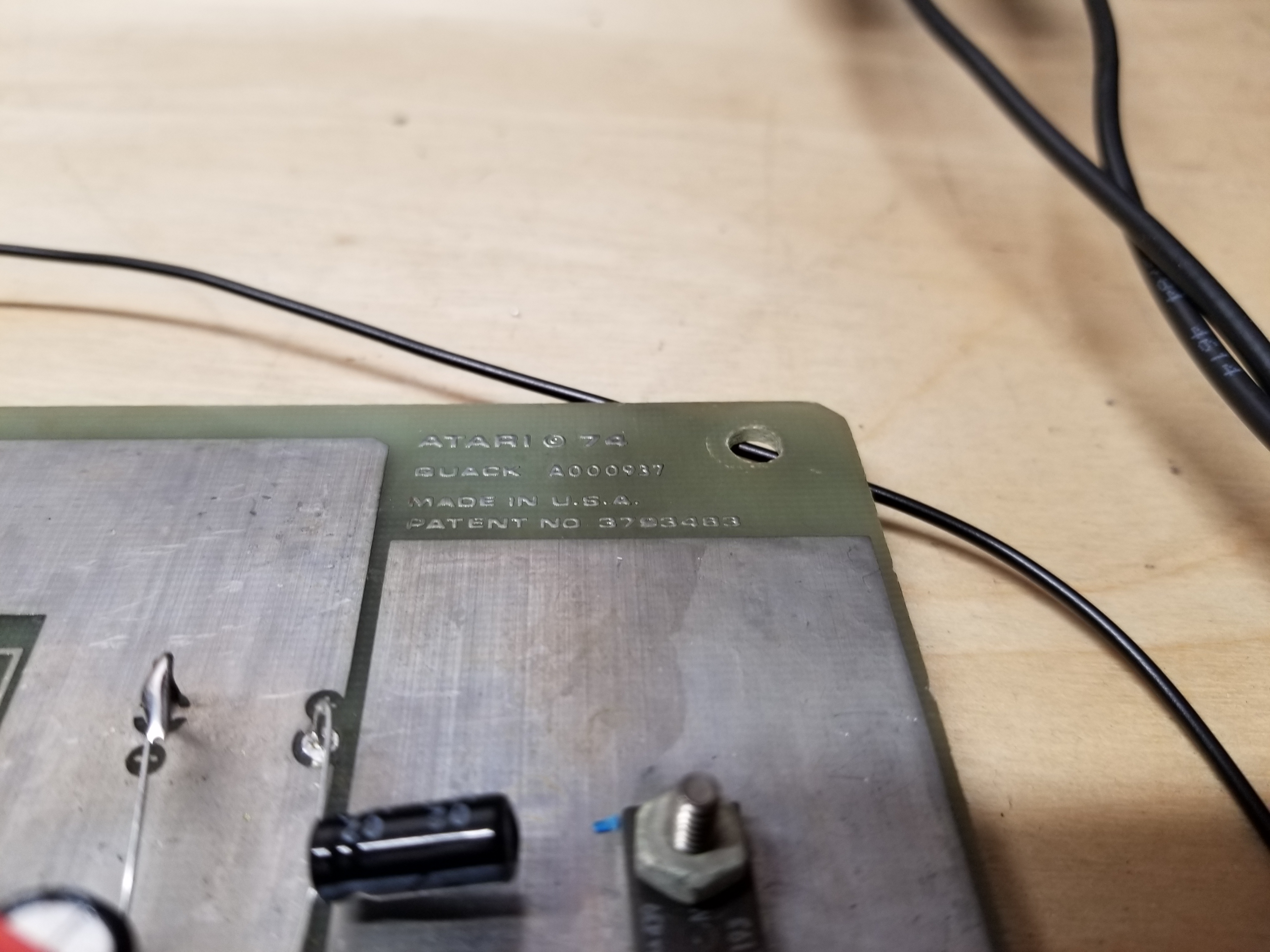
The schematic on the internet is for the Revision - "F".
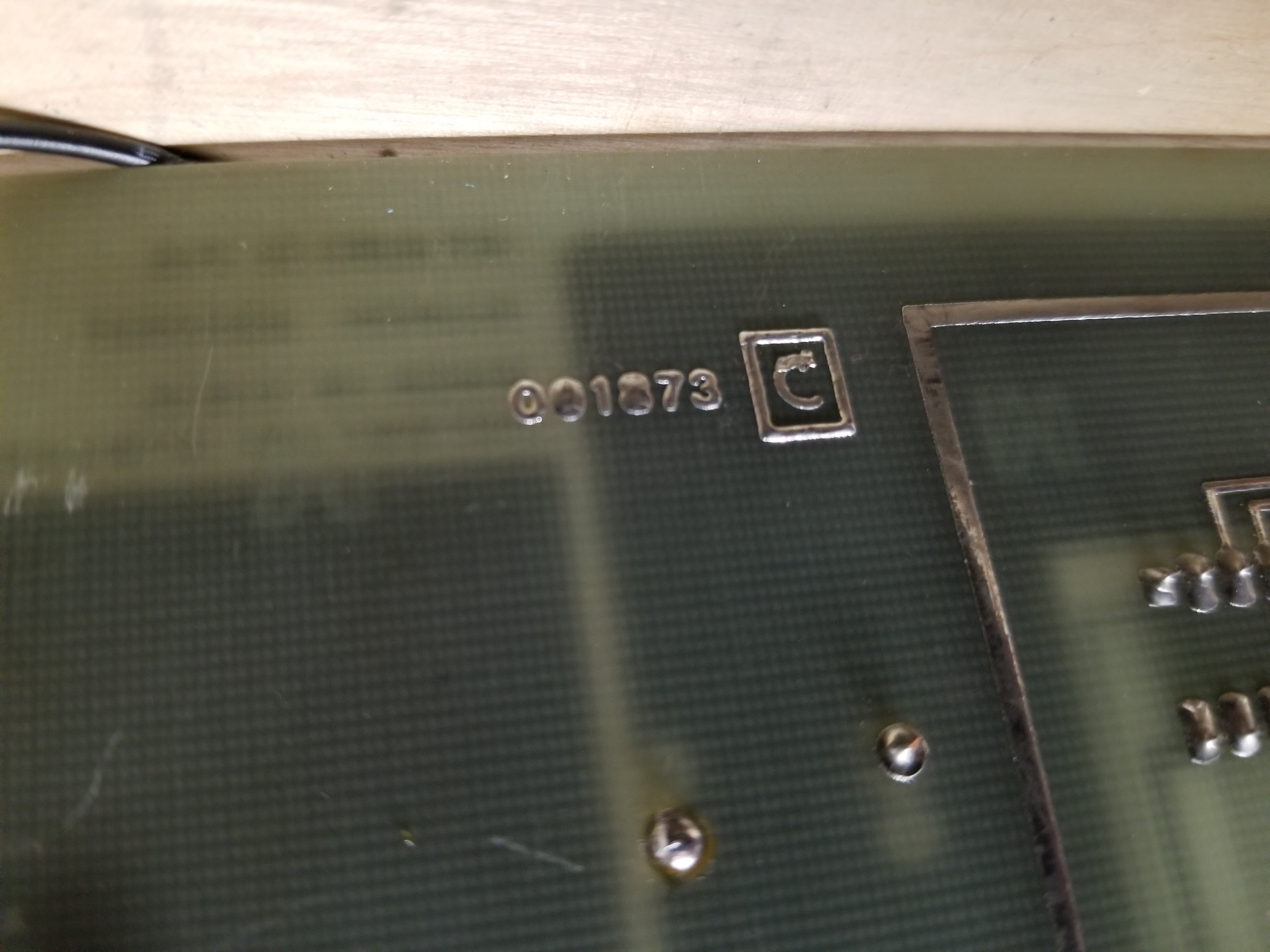
From looking at my board, I have the earlier Revision - "C".
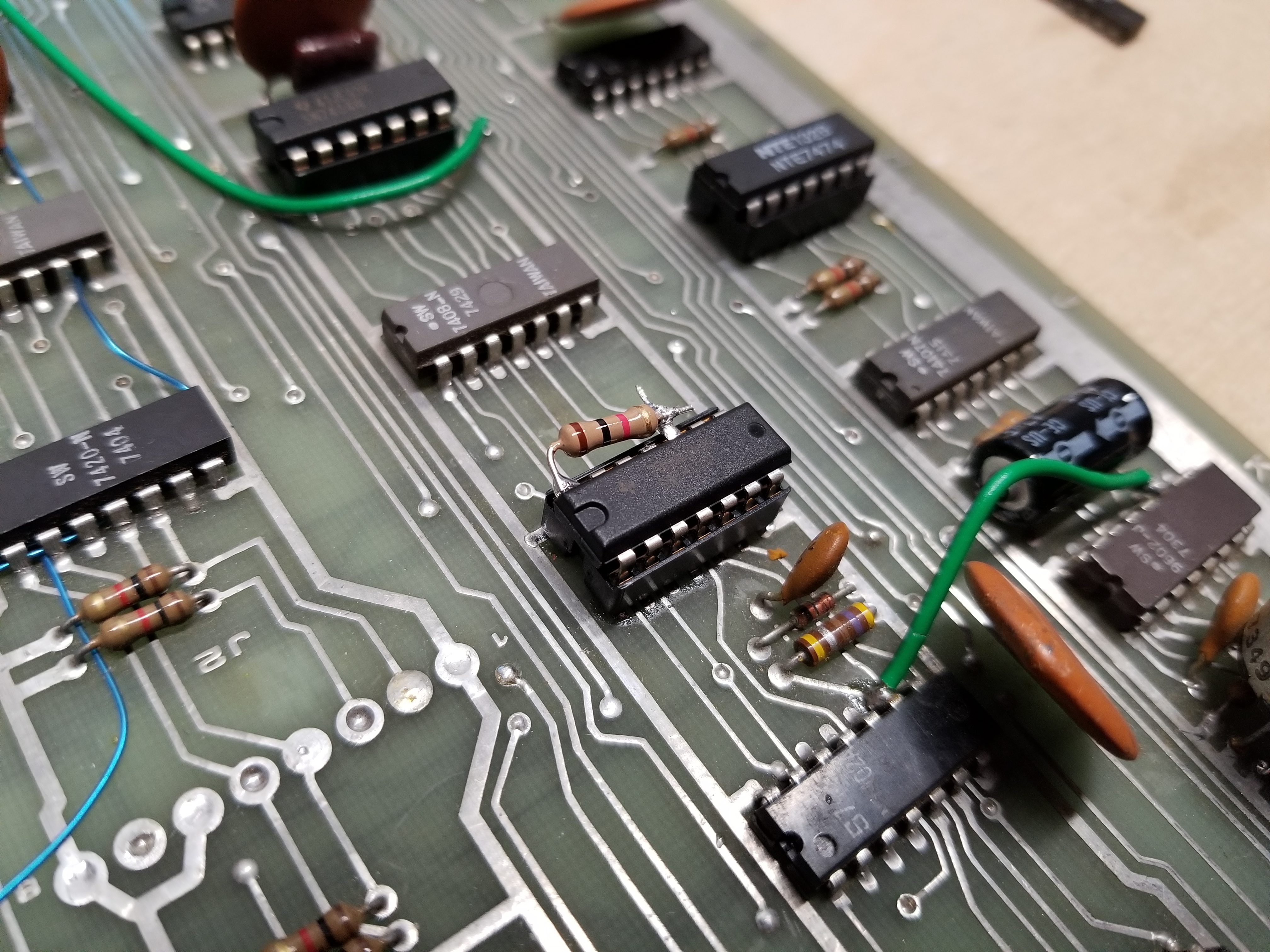
(I have already done some repairs to the board.)
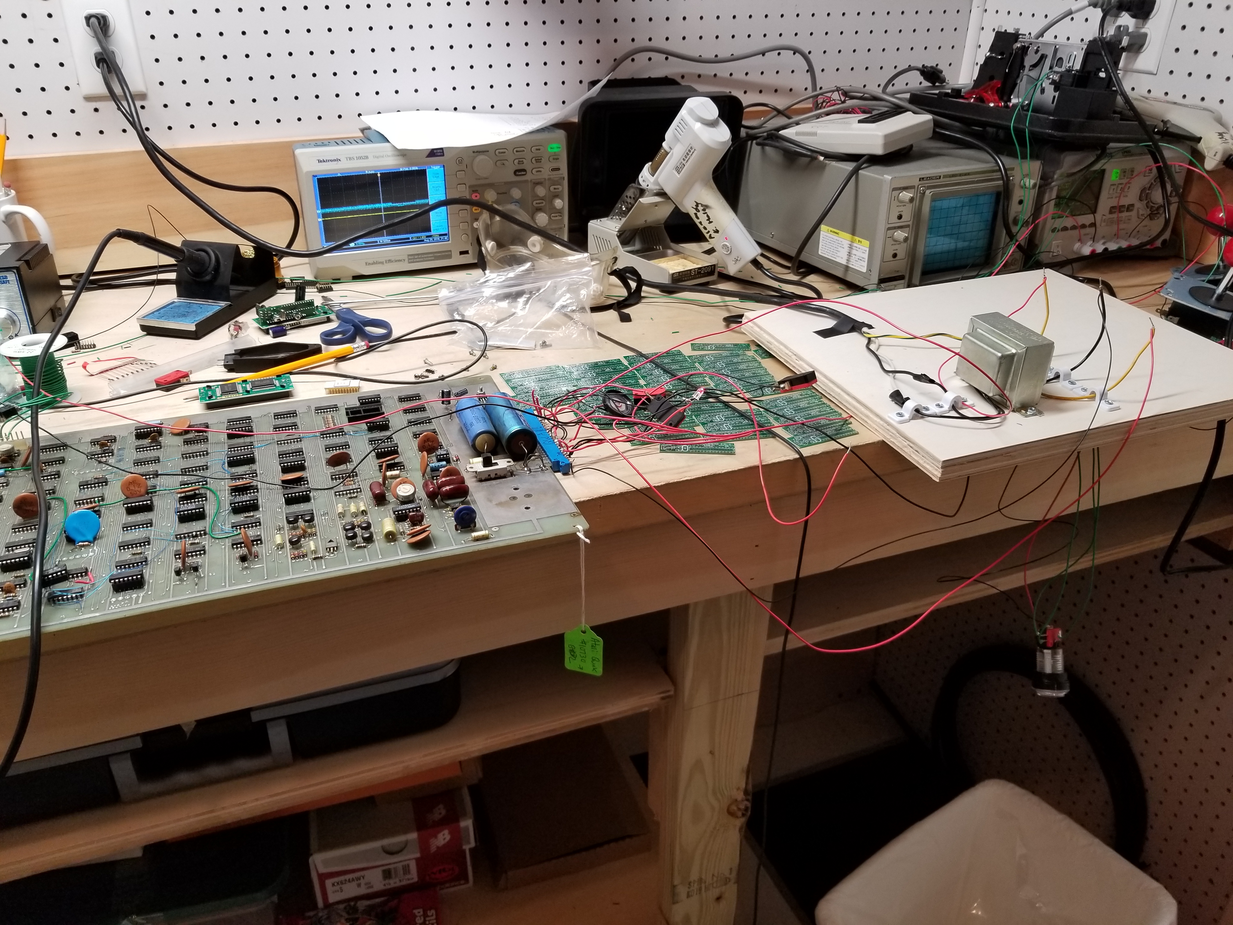
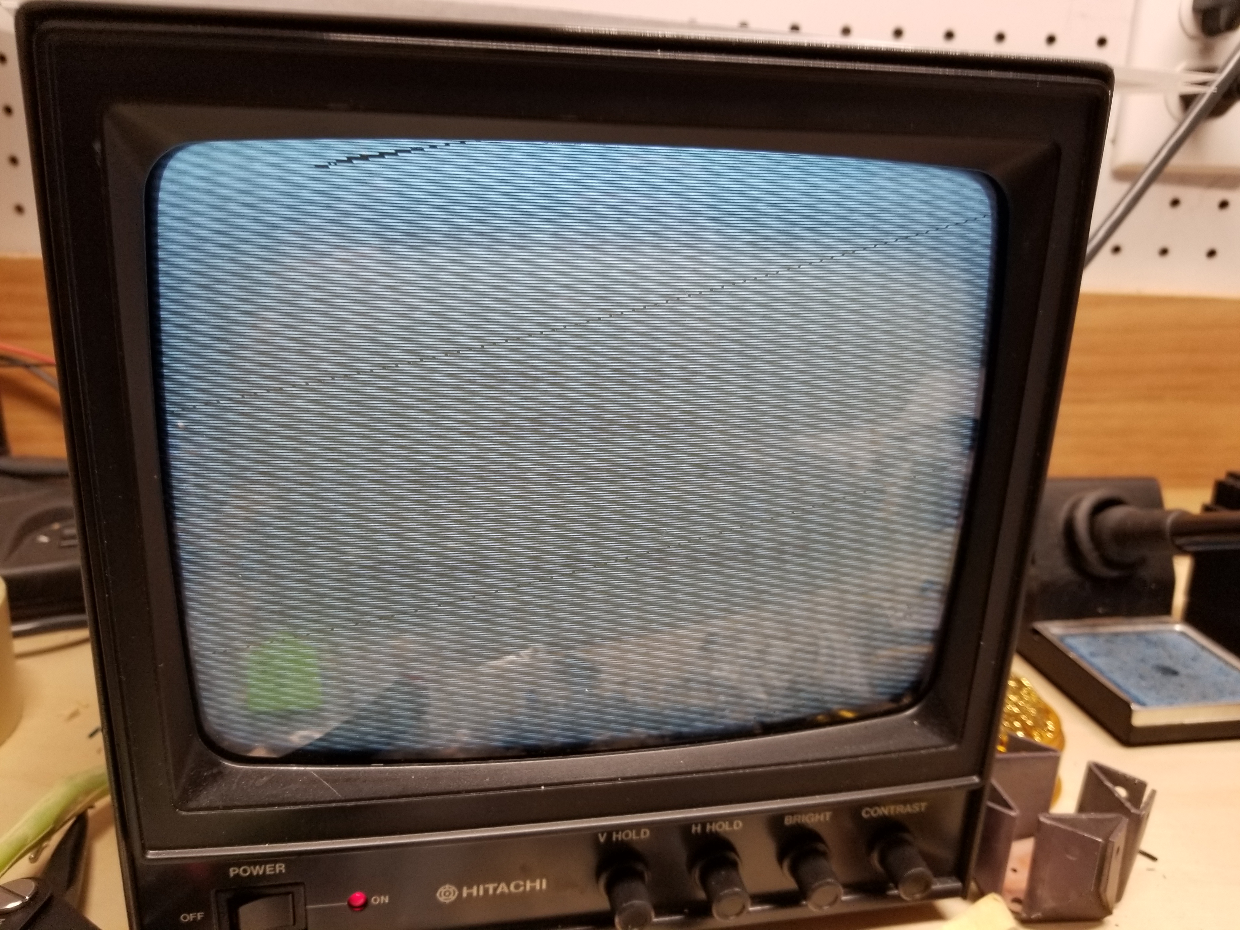
After I made a test rig, this is what appeared:
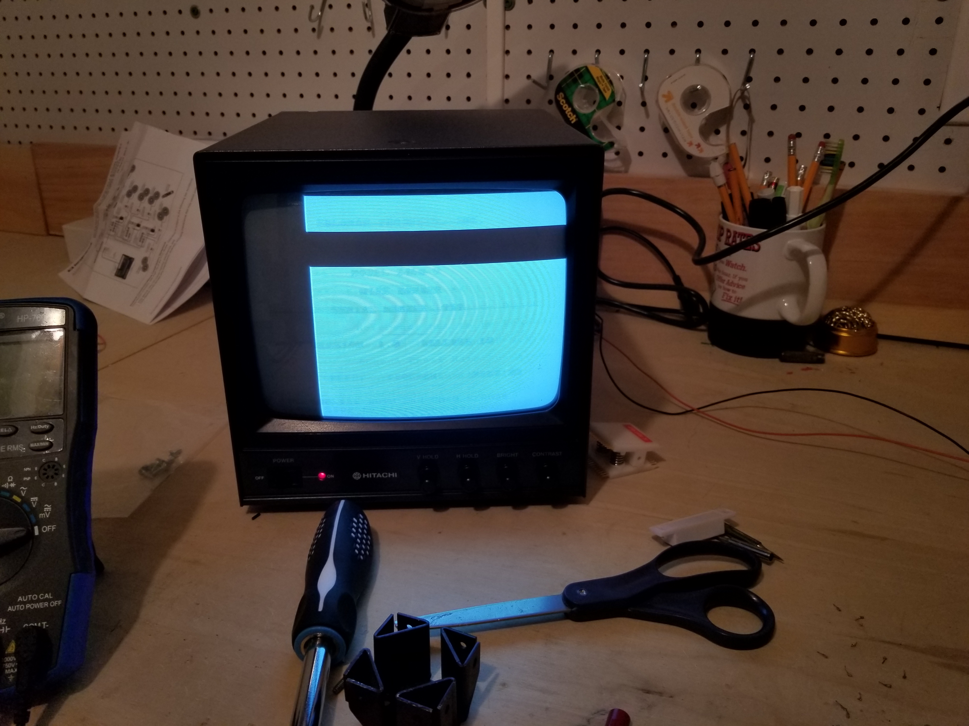
It's not impossible to tell, this board has problems.
- No score area
- No buzzing sound complaining that someone stole the light gun.
- No sound
- No duck
- The screen is not a solid grey
Later, I discovered:
- No ROM Output
- -12 volts is not present
- The duck is there, but something about the enable isn't right...
- The game can't be coined up
Since this was before I became proficient at TTL by creating PERISCOPE, I was very clueless but optomistic about fixing this.
So, I just started piggybacking chips. That was literally my method of finding bad chips. Go me.
Later, I was able to realize that I wasn't going to get the game working without the -12 volts being outputted by the negative voltage circuit.
So, I began focusing my efforts there.
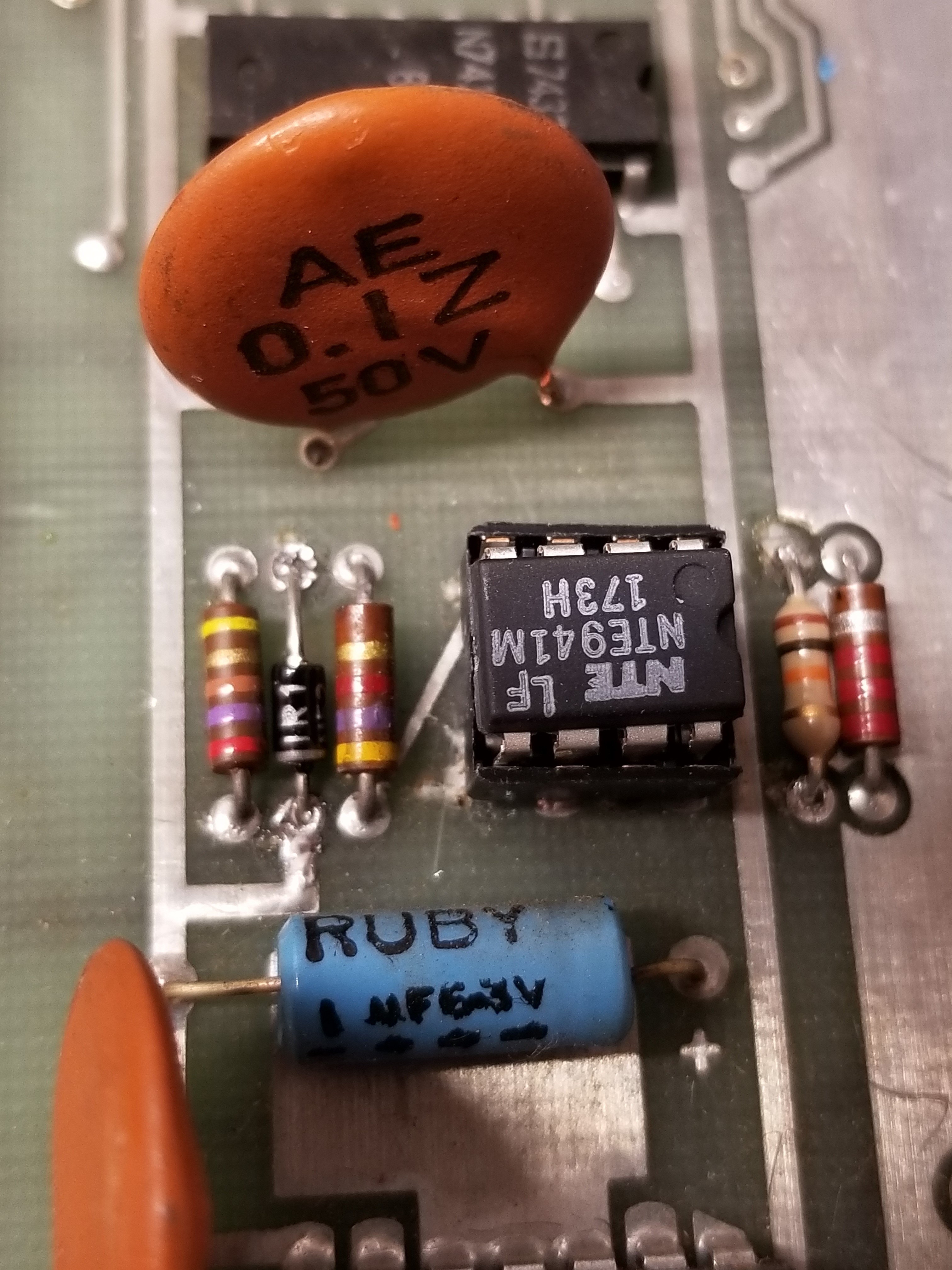
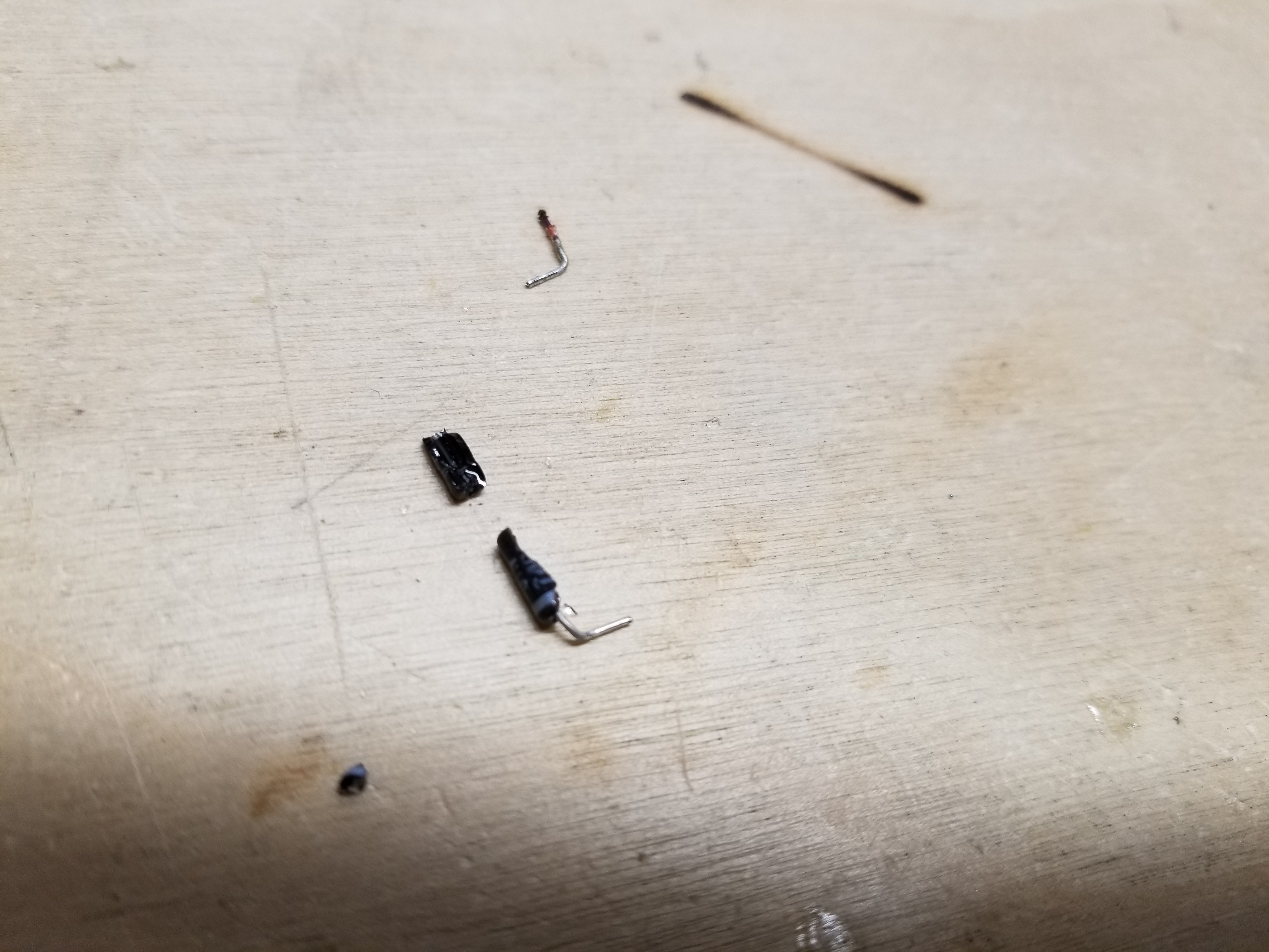
After replacing (almost) all the capacitors in the negative voltage circuit, I decided that I needed to replace the zeener diode, and the ua741. It was after that, I realized that a replacement for the ua741 was the NTE941M. I replaced it and the zeener diode.
While replacing the zeener diode, I realized there was some wierd sort of resistor put where the diode was supposed to be.
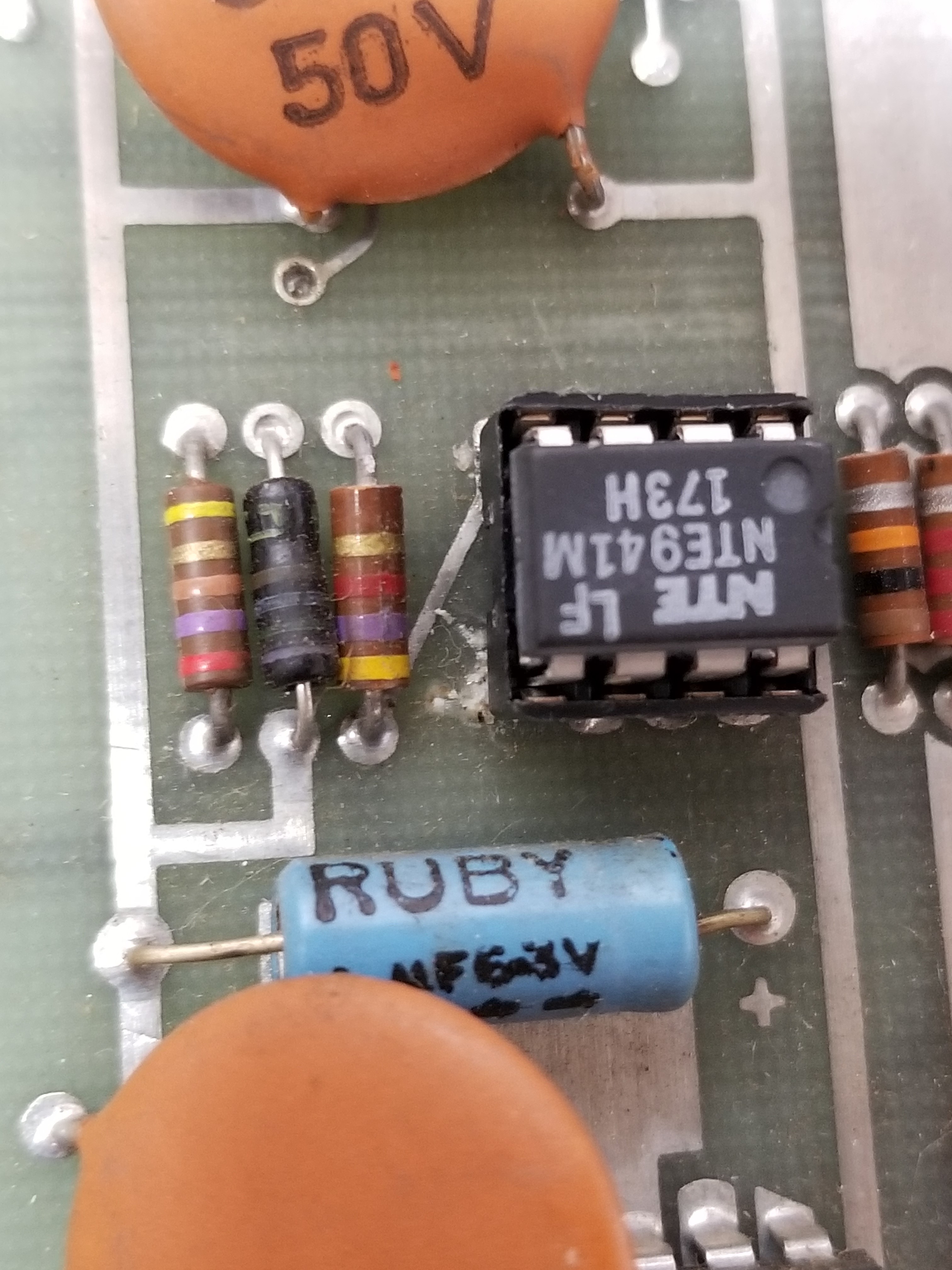
See? That is clearly a diode symbol.
Boom. Replaced.
After replacing all that, it still didn't work.
By the way, I feel I should mention that this all is happening about half a year after I bought it, and after I replaced about 20 chips... [Insert sheepish grin :)]
Anyway, I'm out of ideas. I replaced the first capacitor in the circuit, but there is no negative voltage present there.
There is a transistor, Q1, at the top right of the board. All of the pins are reading ~1 volt, so maybe I need to replace it?
If that doesn't do it, I don't know what will...
Help me, Obi-Wan-Ken-2N5193/NTE185-Obi. You are my only hope.
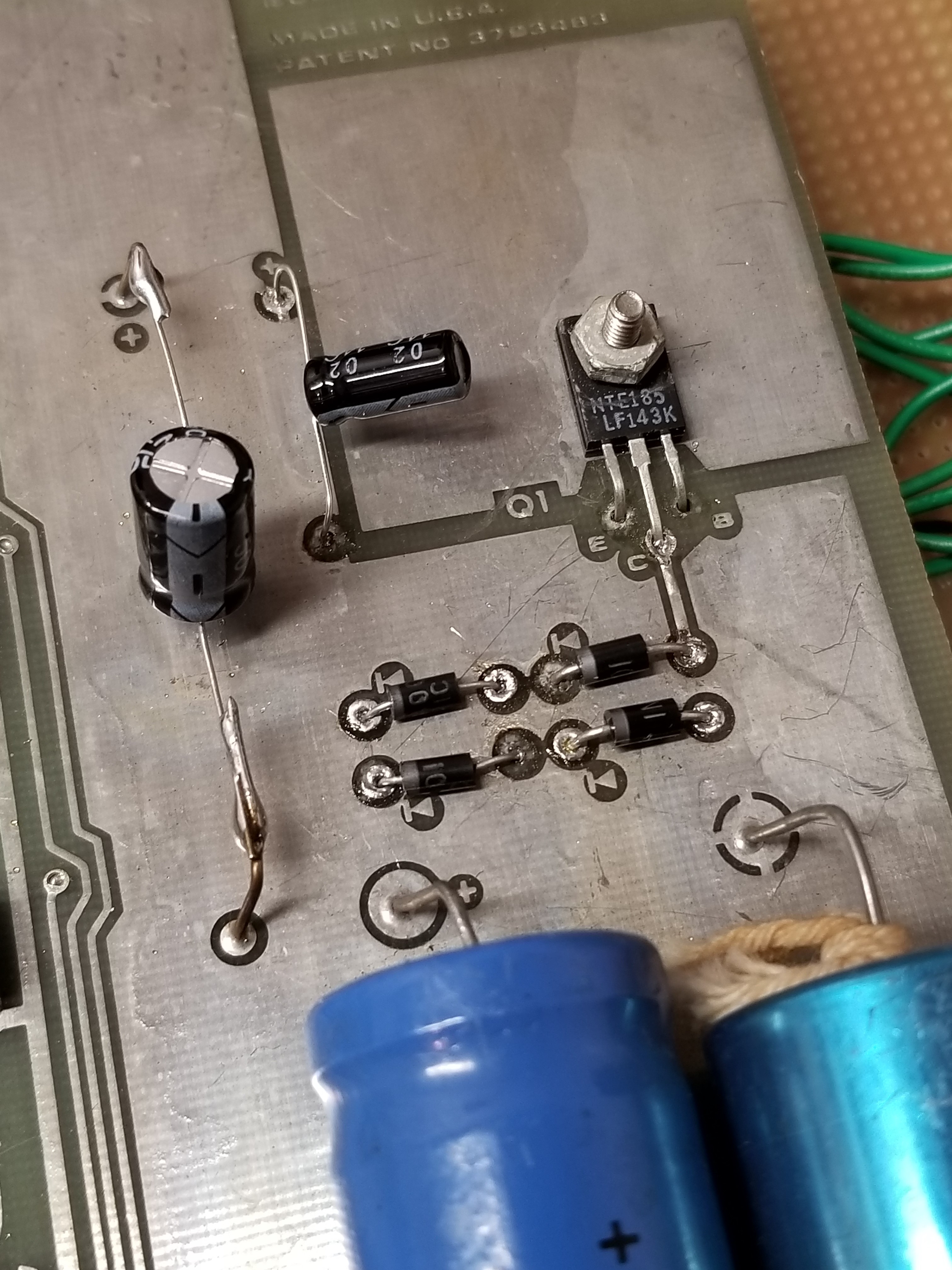
I replaced it, and it still doesn't work. Where is a nuke gif when you need one?
I should probably mention that unconnected pads come off easily when desoldering.
(Hey? It's not like I'm trying to damage my board or anything. I'm looking into alternatives for sucking up solder to see If I can prevent that.)
Okay. I have (unintentionally) shotgunned the whole negative voltage circuit. It still doesn't work.
Maybe there is some other reason why it doesn't work?
At this point, it occurred to me that I have never seen a negative voltage circuit with a straight-up DC power supply input. They always have used an AC supply. I am using a DC benchtop power supply. Maybe that's the problem?
I read the section on negative voltage supplies in Practical Electronics for Inventors by Paul Schertz and Simon Monk, and it basically gave me the message that you can never use DC power supplies to power a negative voltage circuit.
A few months passed. I couldn't find a 25 vac center-tapped transformer.
And yet something about those searches for center-tapped transformers bothered me. I saw "25 VAC" center-tapped transformers, but they were 12.6 - 0 - 12.6 volts. I knew those couldn't be the right thing because Atari QWAK! used those voltages to make 18 volts DC. (It turns out that combining two-phase AC through a full-wave rectifier can do that. I did not understand that back when I was fresh out of middle school.)
Since I already had a transformer that was to those specifications, I decided to try it in case I was wrong. I figured it wouldn't work because I thought I needed a 25 - 0 - 25 volt ac transformer.
I turned it on... and nothing happened. Just the weird white bar on the screen. Just in case my ROM was bad, I used my oscilloscope to test and see if the negative voltage was working.
AND IT WAS!!!
I quickly coined up the game and I heard these lovely noises:
The QWAK! noise. Not working.
The gun stolen siren. May not be fully working, but I don't know.
The gunshot noise. I think it is correct.
(I was shorting some pins together to get the gunshot noise.)
On some websites, the description of QWAK! said that a little square would appear where your shot was placed. I looked at the schematics awhile back, and there was one circuit I didn't understand. I thought nothing of it. I saw nothing that indicated that feature.
But then I fixed the negative voltage circuit. And that all changed:
I still have no light gun to test the game, so I am just shorting wires together. That is why the square shows up in random places.
Getting the negative voltage circuit to finally work was a bittersweet moment. While I had just heard the sound for the first time, it also verified that my ROM was dead.
My oscilloscope also verified that. Good inputs, no output. I made sure it was enabled, and it was.
This dog will not hunt.
But I really want to be able to play QWAK!
That leaves one thing that I can do: Reverse engineer the ROM section of the game, and design my own ROM.
I considered using an arduino, but that would be too slow.
I considered using 16 of my leftover 82S23s to make a new ROM. But then I designed it in my head and realized that it would take more than 50 chips to accomplish.
I even considered making my own diode array to replace the ROM. That would be too huge.
So, I can either buy a new ROM, which would be nigh-impossible.
Or, I can buy some (larger) Bipolar ROMS and make my own programmer and daughter card.
Stay tuned.
Fixing Atari's QWAK (1974) (For real this time)
Alright; it's officially been more than two years since I last did anything with this board. One day, I was mowing the lawn and thinking about my recent success with fixing Jet Fighter. I decided that it was time to finally fix QWAK! once and for all.
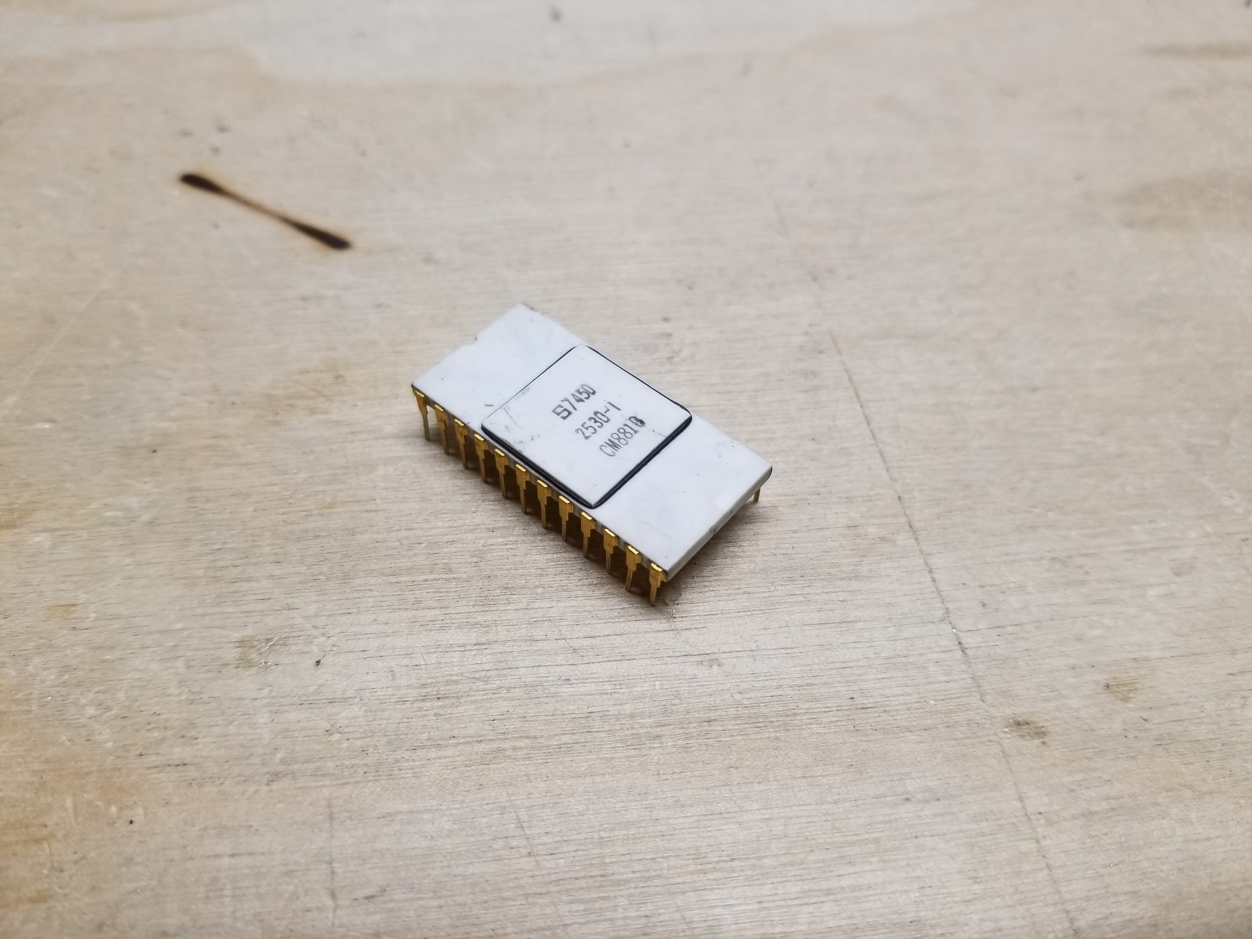
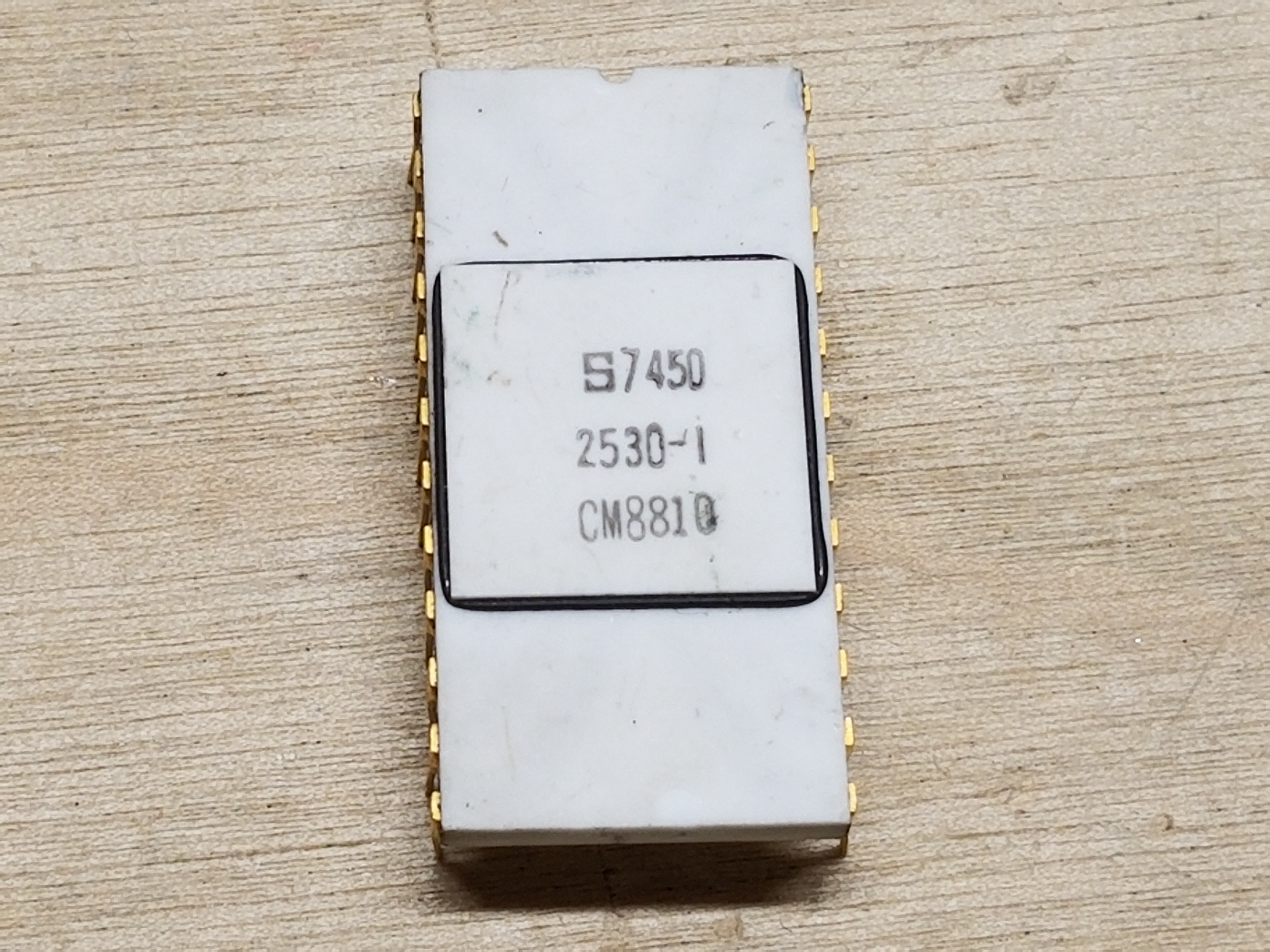
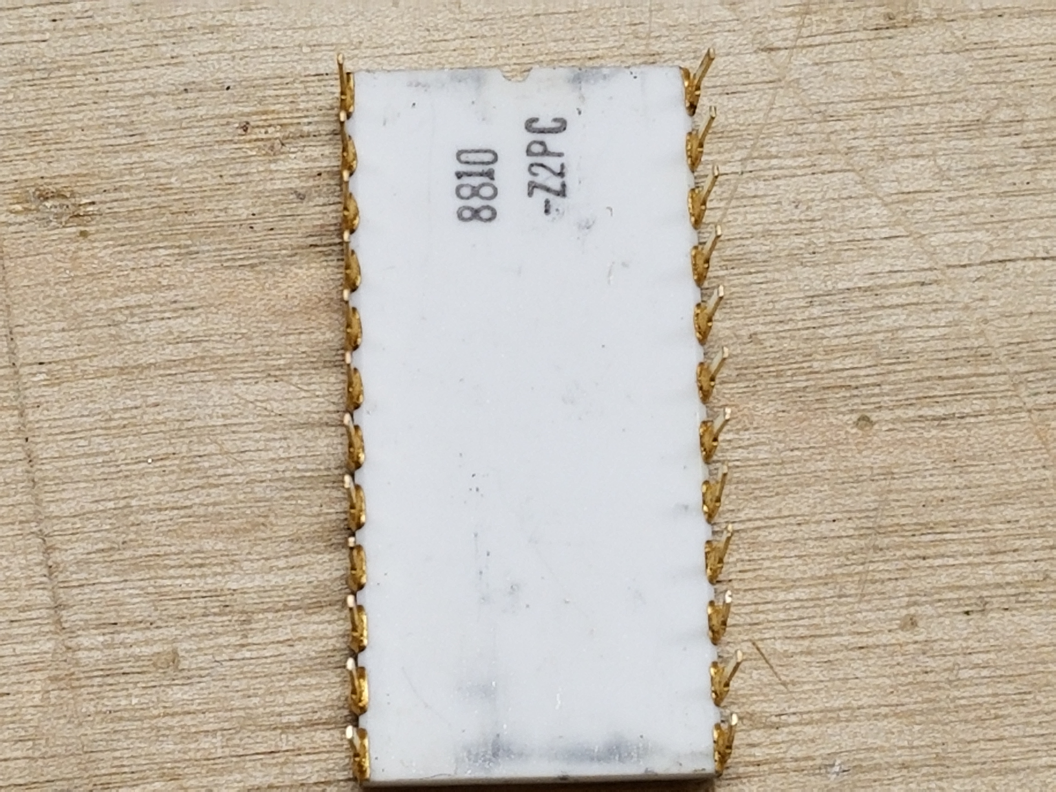
I still faced the same problem that I had before. The mask ROM in my game was dead, and without some workable alternative, my board was going to remain dead. However, I learned a lot while designing the Kincaid Arcade Vector Graphics Card and fixing Jet Fighter, so I had some fresh ideas for how to proceed. Jet Fighter used really fast PROMs like in other games, but even access times of 150 nanoseconds aren't fast enough to be able to race the beam. The designers got around this by loading the ROM data for the line into shift registers, which shifted each pixel onto the screen at a rate much faster than they could be directly read from the ROM. I knew that Gran Trak 10 and QWAK did the same thing. Furthermore, I knew that Gran Trak 10 did it with a mask ROM that had an access time of 1,000 nanoseconds. Since QWAK also used a mask ROM, I figured it would have a similar access time. (I did some research in a TTL data book later, it appears it is actually 500ns for QWAK's S2350.)
...And with 500+ nanosecond access times, it means that (drumroll, please!) I can use a super-duper slow 2716 or 2732 in place of the original ROM!
I still had one problem, though. I don't have the ROM data. I also did not know where to get a dump of the ROM, either. Fortunately, I had an idea of how to circumvent that. The memory in the mask ROM is arranged as 512 x 8. I figured that if I loaded 64 8x8 pixel symbols into an EPROM, I could figure out what symbols corresponded to the game objects, and by extension, their associated locations in the EPROM. After that, I'd just have to draw my own graphics.
However, I wasn't too excited about doing something like that. Drawing 64 8x8 symbols on graph paper would be difficult. Converting 8 bits to hex, 512 times, would be difficult. Transferring them to a .bin file and loading them onto EPROM would still be difficult. There had to be a better way to do this.
So, I checked one last time to see if the ROM dump was anywhere on the internet. Against all odds, I found the TTL dump for OUTLAW, but not QWAK! However, I did find that somebody on the internet had actually dumped the ROM. ArcadeItalia.net showed that Ed Fries had dumped the ROM. So, I sent him an email asking if he would be willing to send me a copy of the ROM dump so I could fix my game. He told me that he collaborated with Tim "Teeray" Giddins in getting the ROM dumped, and kindly attached a copy. Later, he also told me that John's Jukes was selling some NOS QWAK! optical boards.
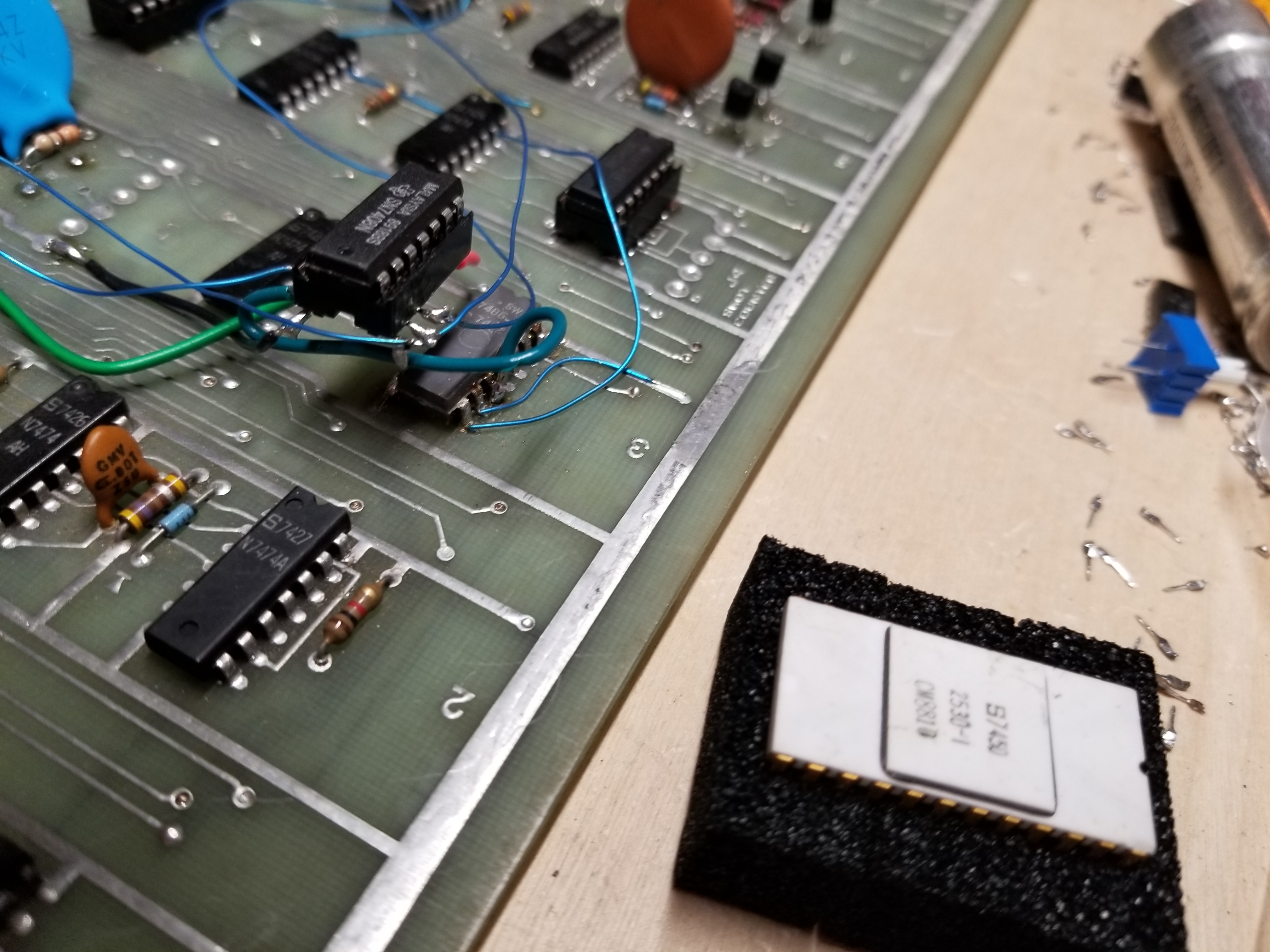
So, with the ROM dump and my GQ-4x4 programmer, I set out to burn the dump to a 2716. I tried and tried many times, and could not get any of my 2716s to program. Not even with an external power adapter. After reading around the internet, I found that 2716s always give people trouble, and they just use 2732s or some other part instead. I happened to have a whole buch of 2732s on hand from getting ready to start designing the processor that would interface with a previous project, the Kincaid Arcade Vector Graphics Card (Alas, that will not happen this side of college.) The 2732s worked on the first try. I ran downstairs to start wiring up an adapter that would allow the 2732 to plug into the spot for the 2530.
This is what I came up with:
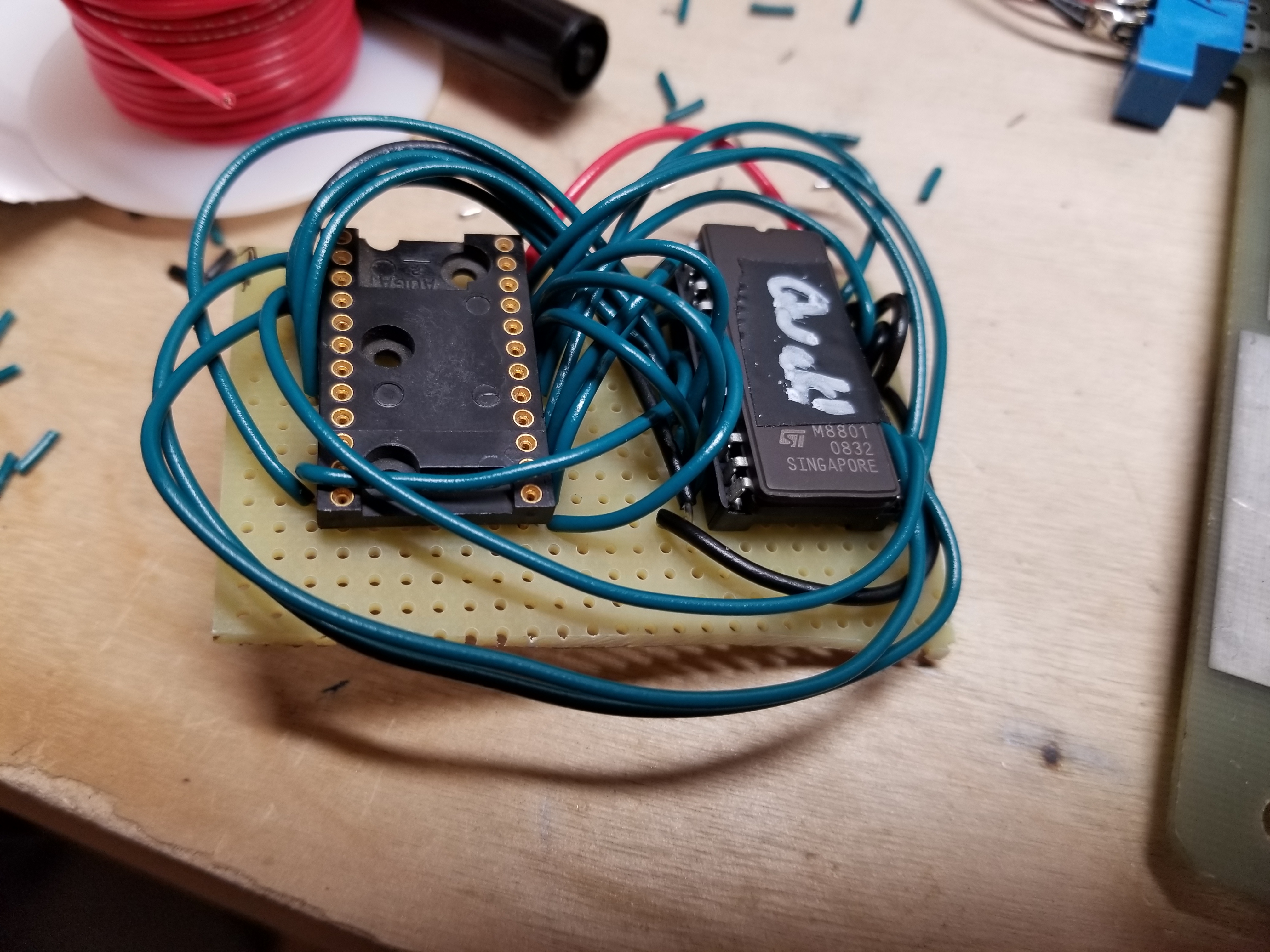
(I used a 24-pin wirewrap socket so I could plug it into the board.)
Then came the moment of truth... I plugged in the adapter:
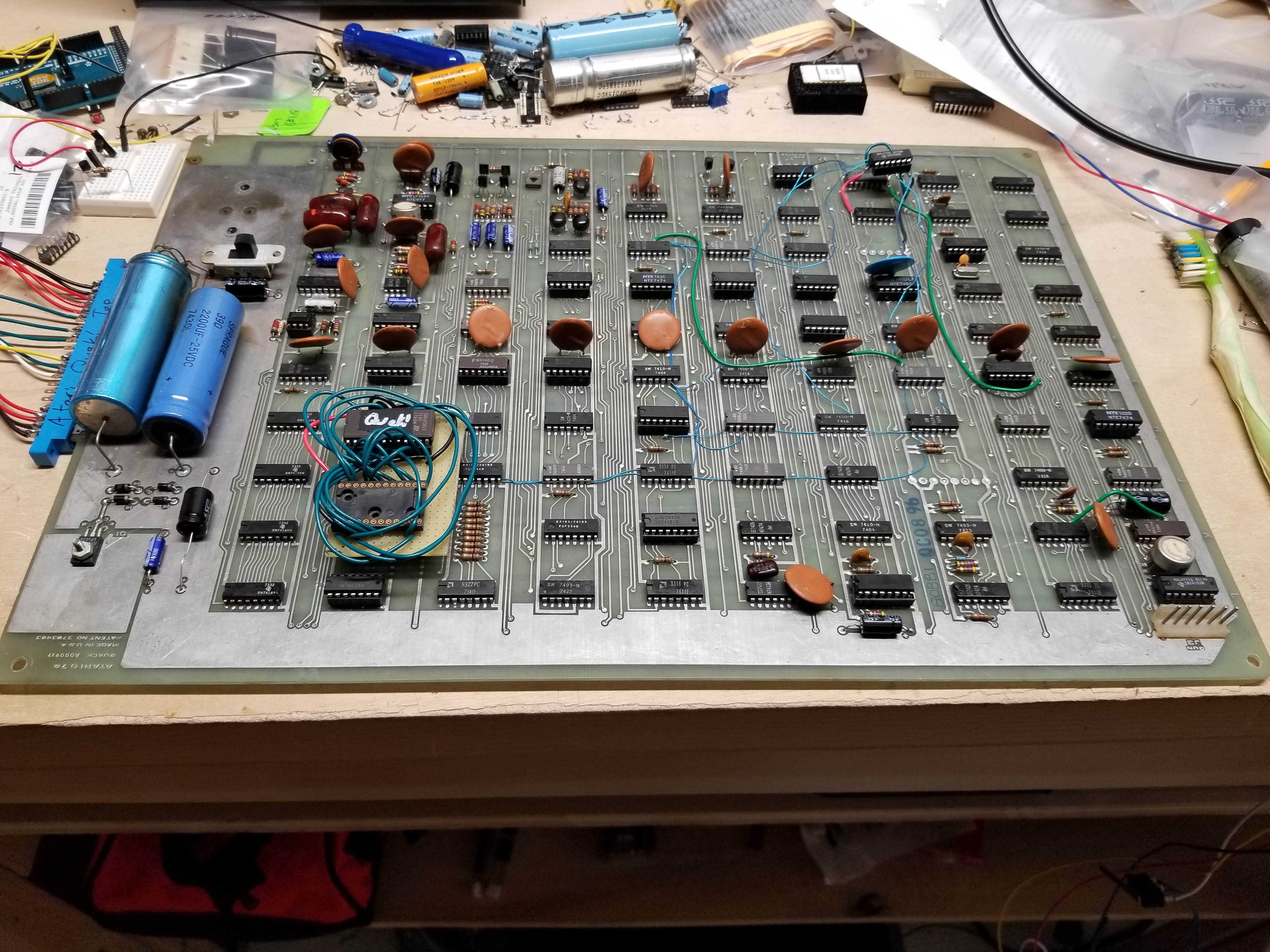
And turned it on...
HALLELUJAH!
There were still several issues with game, as well as several new ones that arose during the years it sat on my PCB shelf.
When I pulled it out of my PCB shelf for the first time in awhile, a little slip of paper came out too. Several years back, I had written down a bad chip that I had found, but had decided not to replace it since the game was not going to be working again anytime soon. Pin 5 of the 7474 at H1 was floating. No wonder I didn't replace it, it was in the light gun circuit, and I didn't have one. I replaced it, and was greeted by the lovely song of the light gun stolen siren:
Ow... My ears...
The next issue I worked on was why the ducks were being counted vertically on the left side of the screen. Obviously, that wasn't right. I checked the signals that formed the vertical window for the score area and found that the 64V signal was missing. Interesting. The sync chain still counts properly, and I have already replaced that counter chip (7493, E4). I lifted the pin and discovered that there was a short somewhere else on the board. Great. Now I have to search for every place 64V is connected to in the manual...
Before I did that, I wanted to make sure that it didn't have anything to do with a wire mod, so I did a continuity test. None of the jumpers were connected to 64V.
I checked the manual, and only found two places where 64V was used. The chip at E9 (7427) that generated the vertical window for the score was one of them, so I replaced it. The short was still there. The only other place the signal was located in the manual was at D7 (7420). I went to replace it and found that I had already replaced it and socketed it. Wait a minute. I put a 7404 there. Maybe the REV-C board had a different chip? I did a continuity test with my multimeter and discovered that it was correct. I swapped it with a 7420 and it worked again. I still can't believe I managed to put the wrong chip in a spot after replacing it previously. That's just so embarrassing. :)
I went to work on the missing gunshot noise and discovered that there was no white noise at pin 9, B9 (4136 / NTE997 op amp). I replaced Q5 and Q6, but that didn't fix the issue. I decided it would be better to wait on fixing the sound since I hadn't recapped the board yet.
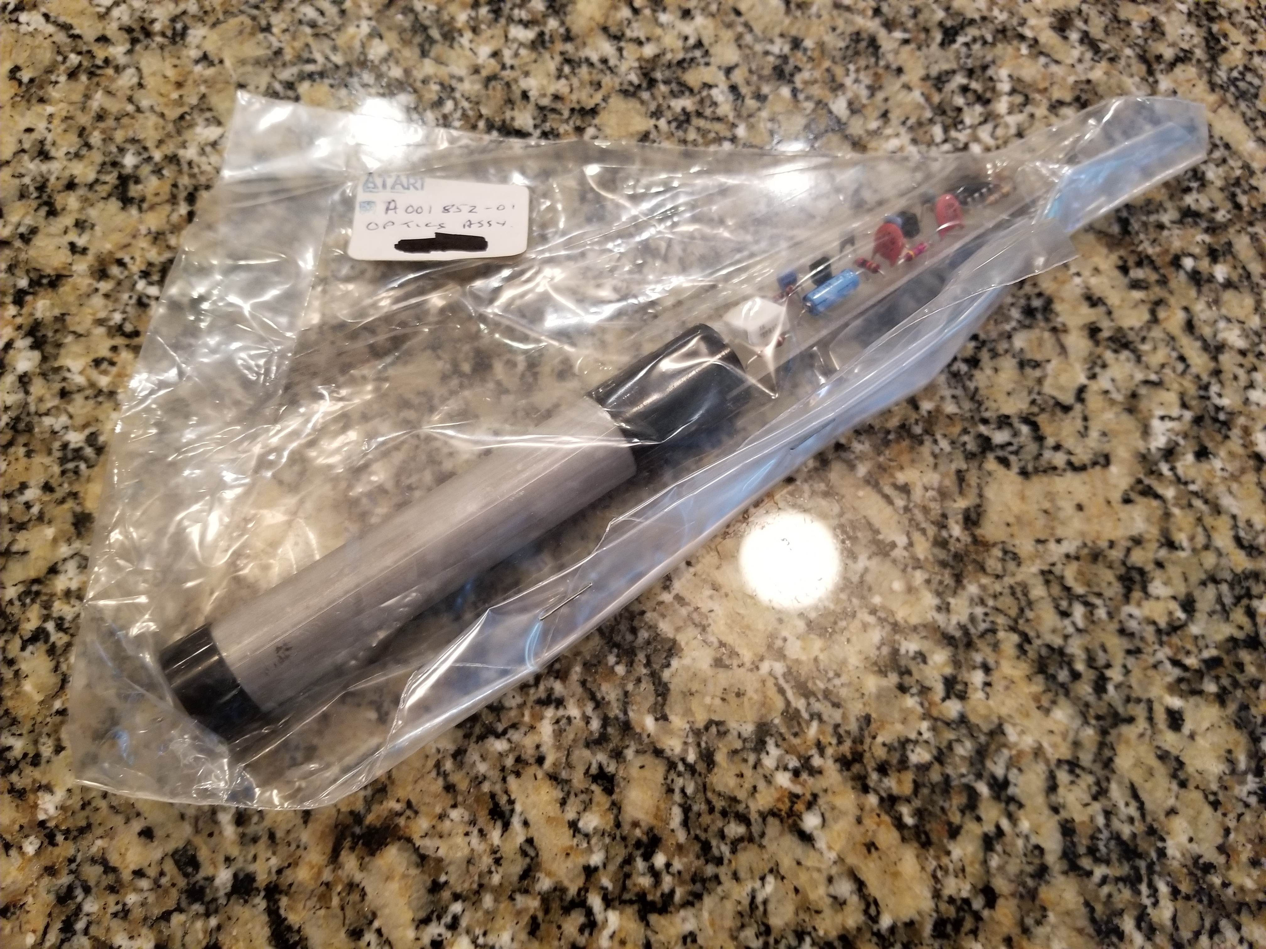
In the meantime, the NOS optical assembly I recieved from John's Jukes arrived. Here's what it looked like when I pulled it out of the box:
(Later on, I also took some pictures of my light gun and optics assembly. Here they are:)
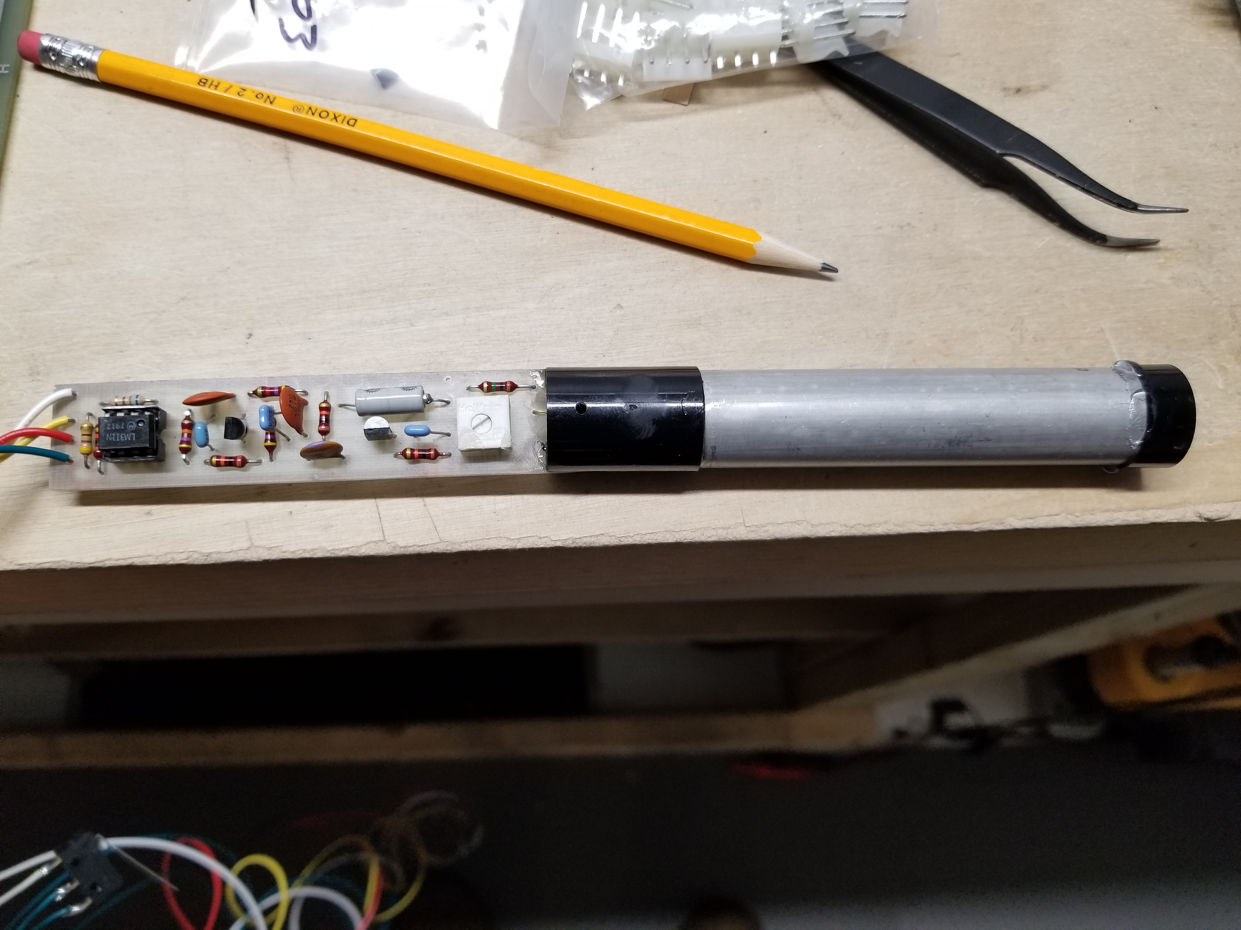
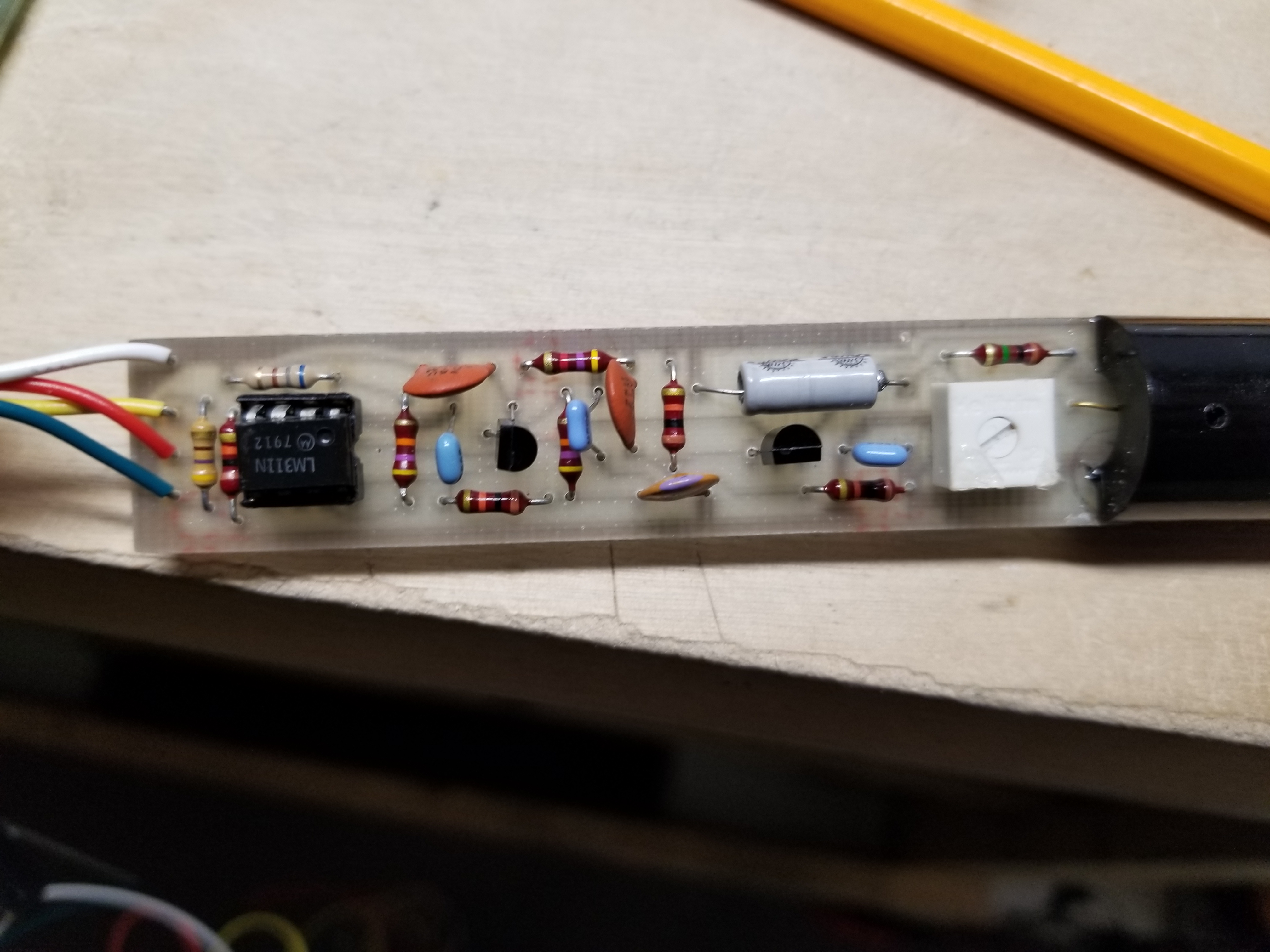
In the emails I exchanged with Ed Fries, he warned me that the lens on the optical assembly was loose and would need to be glued down for consistant performance. Somehow, it didn't occur to me that it was going to be so loose that it would fall off the assembly as soon as I took it out of the bag...
Anyway, I eventually glued it back in place and proceeded with fixing the game. I made a cable to connect the optics board to the PCB and began to test it. It didn't work yet. Great. I tracked the issue on the board to a bad 74107 at L1. All of the outputs were either dead or floating. I replaced it and powered it on:
Come on. Something just had to go bad AT THIS MOMENT?!? Very well, I began to look for the source of the screen's lack of a sync signal. I traced it back to pin 13 of D4 (7402) being stuck low. It was holding the HSYNC flip-flop at D5 (7474) in the reset state. I replaced D4, but it didn't fix the issue. But the output was stuck low and it didn't match the truth table. Why isn't it fixed? I lifted the pin... and oh, great. Another shorted signal. Since D5 had been replaced previously, I pulled it out of the socket and stuck it in my chip tester. It was bad. I put in a new one, and the Horizontal Sync signal was present again.
So I went to test the light gun and... WHERE'D THE STINKING DUCK GO?!? GRAAAAAAAHHHHH! C'mon man. I just wanted to get the light gun working!!! Oh well, I'll fix the duck too. *Grumble Grumble*. I traced the missing duck to a bad gate at F7 (7404). I had previously replaced it, so I yanked it and put it in my chip tester. It was bad. Another chip I had previously replaced went bad... Anyway, I replaced it and the duck was present.
Alright. This time... this time for sure. I pointed the light gun at the screen... and shots weren't registering. So, I began to replace components on the light gun PCB. I replaced the LM311, both transistors, and the only electrolytic. One of the capacitors was cracked and looking a little sketchy, so I replaced it as well. It still didn't work. Maybe there's a slight difference between versions of the LM311 comparator? I did a quick internet search and discovered that there is indeed a difference, and other people have found that you cannot use a LM311P in place of an LM311N. I put the original LM chip back in, calibrated the gun, AND IT WORKED!
So one of the other components must have been bad. It is also good to know that a LM311V or N cannot be replaced with a LM311P on an Atari light gun optics board.
Since I could not hold the light gun and the trigger switch as well as my phone at the same time, I did not record a video yet. I went and tracked down some other issues first.
I recapped the main PCB and went back to work on the gunshot sound. Pin 12 at F2 (7404) would not go above 2.5 volts when HIGH, so I replaced it. As it turns out, the pin was just being pulled down by the analog circuitry, and the chip was good. I naturally suspected the diodes next. I replaced VR2 (a 1N746), and I only had to heat up one pin before it fell apart off of the pcb:
Well that obviously wasn't working...
I replaced it with the NTE equivalent and it still wasn't working. I suspected the MFC6040 since shorting pins 1 & 2 wouldn't trigger the gunshot noise, or any noise, like on the other one. I replaced it with a MC3340, and it still didn't work. I later swapped the two MFC6040s and found that they were both good, so I put them back. I checked all of the capacitors in the circuit, and they were good. I tested all of the resistors in the circuit, and they were good. So I tested literally every part in the gunshot noise circuit, and everything is good. That only left the 4136 op amp, but I had already replaced it. Obviously, I was missing something, but I wasn't too happy at the idea of spending more money to get a replacement chip, so I gave up on the sound. Perhaps it had something to do with that special "noise selected transistor", since there wasn't any noise signal present? But I had already replaced that. Ah, whatever. I hate analog.
(I now know that the problem is that the NOISE signal is missing, and that is because I replaced the Noise Selected 2N3643 (Q5) with a regular transistor. I talk a bit about an article that explains why using a noise-selected transistor matters at the bottom of the Jet Fighter page.)
I played a couple more games and I noticed that I could shoot an infinite number of ducks, and the game wouldn't end. I made sure that the board wasn't jumpered for freeplay, and it wasn't, so I began to look for the issue. I noticed that the ENDSEQUENCE signal wouldn't go high at when the dog ran off of the bottom left of the screen. I looked up the datasheet for the 9314 (at F8), and determined that pin 12 was stuck low. I replaced it and ENDSEQUENCE would trigger when the dog ran off the screen. That still didn't fix the issue. The duck counter still wasn't counting.
I traced the issue back to the 7486 at A3. One of the inputs was floating. Wait a minute. The chip is covered with wire mods. That input wasn't connected to anything. Pin 10 obviously once had a wire mod connected to it. Great. Fortunately, the guys at SCV games (1/5/2022: Link removed; page no longer exists.) had taken really good close-ups of their Revison-C board, so I was able to see what the wire mods were. My fears were confirmed; there was a wire mod connected there. As it turns out, I had connected one of the jumpers from the piggybacked chip to the wrong pin when I replaced it. I moved the wire to the correct spot, and the game finally ended. Thank you, thank you, thank you SCV games. I probably wouldn't have figured out the issue if it weren't for your high-res PCB closeups.
Lesson learned: be very careful when messing with wire mods.
And now, my board fully works, except for the gunshot noise. I'll probably revisit that sometime in the future.
(Update: the issue is because I replaced the noise-selected transistor with one that wasn't noise-selected. The odds of me finding a replacement noise-selected one are very slim, so the sound might not ever be fixed.)
Lastly, I owe a big thank you to both Ed Fries and SCV games. Thank you Ed for sending me the ROM dump, pointing me to light gun parts, and answering other questions that I had about QWAK. And thank you SCV games for putting up high-res pictures of all aspects of your QWAK! game up on the internet.
Gameplay Videos
This is the first gameplay video of QWAK! to be put on the internet that shows the duck buzz-bombing and the dog picking it up.
Thanks for recording the video, Dad!
Later, I got sick of the "3 shots per duck counter," so I disabled it.
I find it hilarious that I still can't hit that duck even with 20+ shots...
Calibrating The Light Gun
The light gun certainly isn't the best part about QWAK. It is quite a finicky piece of technology. Getting the light gun to consistantly register shots on the screen requires that you adjust both the light gun and the monitor. Even so, where the shot lands on the screen is also dependent upon whether or not the guy who was stuffing the boards had the photodiode angled ever so slightly when they placed it...
Before you even adjust the gun itself, you must have the monitor brightness turned up as high as possible. I have tested and found that monitor brightness greatly affects the gun's ability to place a shot, but ambient light has no effect whatsoever. It does not matter if the lights are off or on. You should also make sure that the contrast is adjusted so that the screen is as bright as possible with the duck still looking black.
There is a potentiometor on the light gun board. This adjusts the sensitivity of the light gun. Point the gun at the monitor and have your oscilloscope show you what the output pin is doing. When the gun is properly adjusted, the signal should look like this:
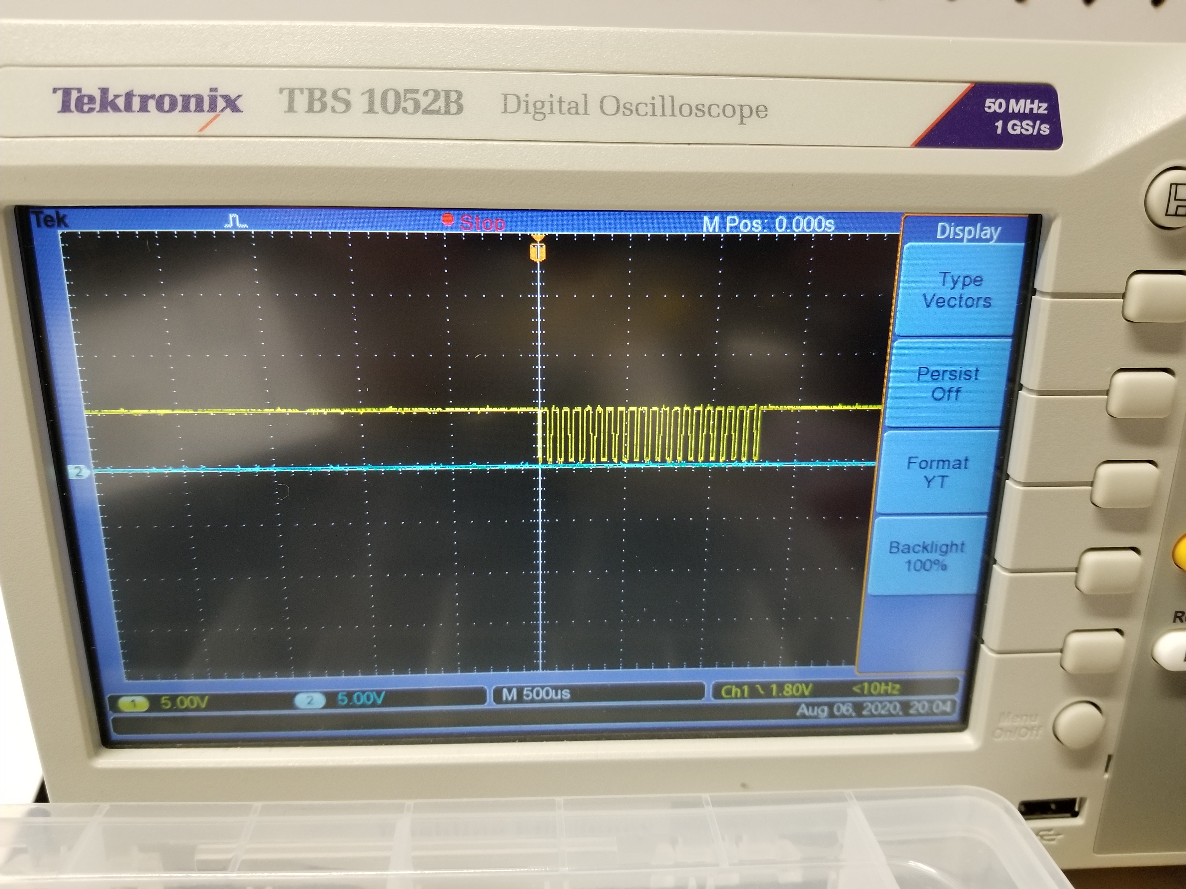
Be advised: the gun optics board is very sensitive to static. If your finger touches one of the traces, it will make the output signal have millions of those little spikes even if the gun is not pointed at the monitor. The game will not register the shot even if it is pointed at the monitor.
I have found that the optics gun registers shots the best when the lens is held somewhere between 8" and 14" away from the screen. It will still output a signal at longer ranges if well-adjusted, but the signal will be flaky and the PCB probably won't register the hit very often (I tried this between 14" and 2' of distance).
There is also a potentiometer on the PCB near where the light gun connector is. I have found that it adjusts the PCB's responsiveness to the shot. If the potentiometor is spun all the way to the right, the shot will always land at the same spot, regardless of where the gun is pointed on the screen. At the other extreme, the shot follows the light gun freely.
Disabling the Shot Counter
For those of us who own QWAK! boards or cabinets, it can get pretty frustrating when the game decides it's never going to register a shot, or it's going to place your shot pretty far to the right of where you aimed. After I finished assembling my "Reproduction" Atari Outlaw Light Gun Casing, I got tired of trying to hit the duck when half of my shots wouldn't register. I wondered if it would be possible to disable the "3 shots per duck counter," so I took a look at the scan of the manual for the game. As it turns out, it is actually quite easy. All I had to do was lift pin 10 of J2 (7400) and solder a 1K ohm resistor between it and +5V like shown in the pictures below:
(This paragraph is an explanation of how the mod works.) The "3 shot per duck counter" is made up of the 74107 at J1 and the 7400 at J2. The two flip flops in the '107 are chained together to form a two-bit counter. The counter can have values between 0 and 3. When the counter has a "3", it outputs 11 (binary). This binary number is fed to a NAND gate at the 7400, which only outputs a zero when both inputs are at 1. This means that the NAND gate outputs a logic 1 when the player still has shots left. So, if I lift the pin and connect that trace to +5 volts through a pullup resistor (adding a pullup is good practice when connecting a TTL input to voltage), then the game will think that the player still has shots left. To see a video of it in action, scroll to the "Gameplay Videos" section above.
Now that I think about it, it would be sort of hilarious if I added a counter that allows me to just press and hold the trigger and have the game go full-auto. Maybe I should also add a solenoid for recoil... I could call it "Tommy Gun Duck Hunting" or something like that.
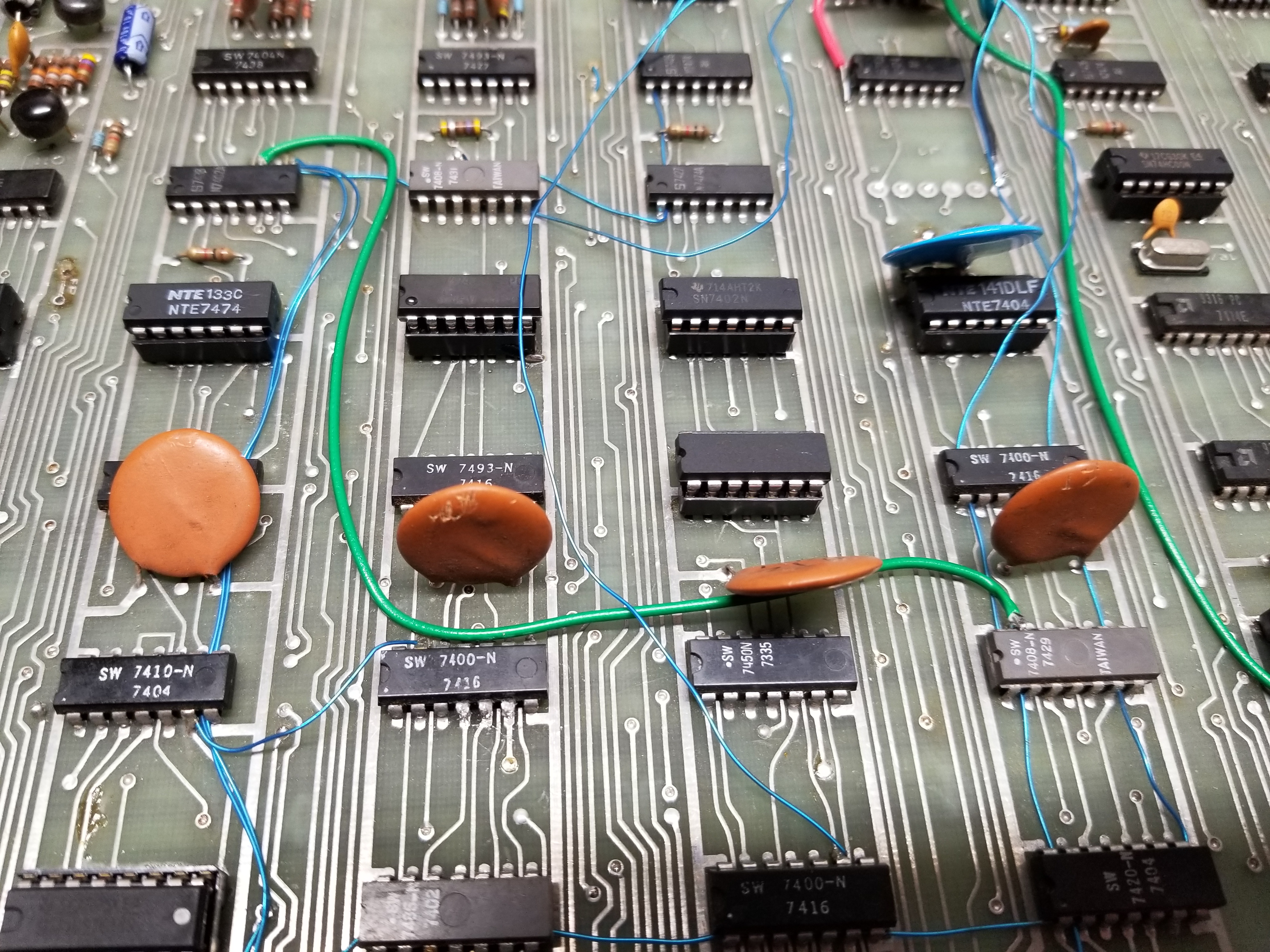
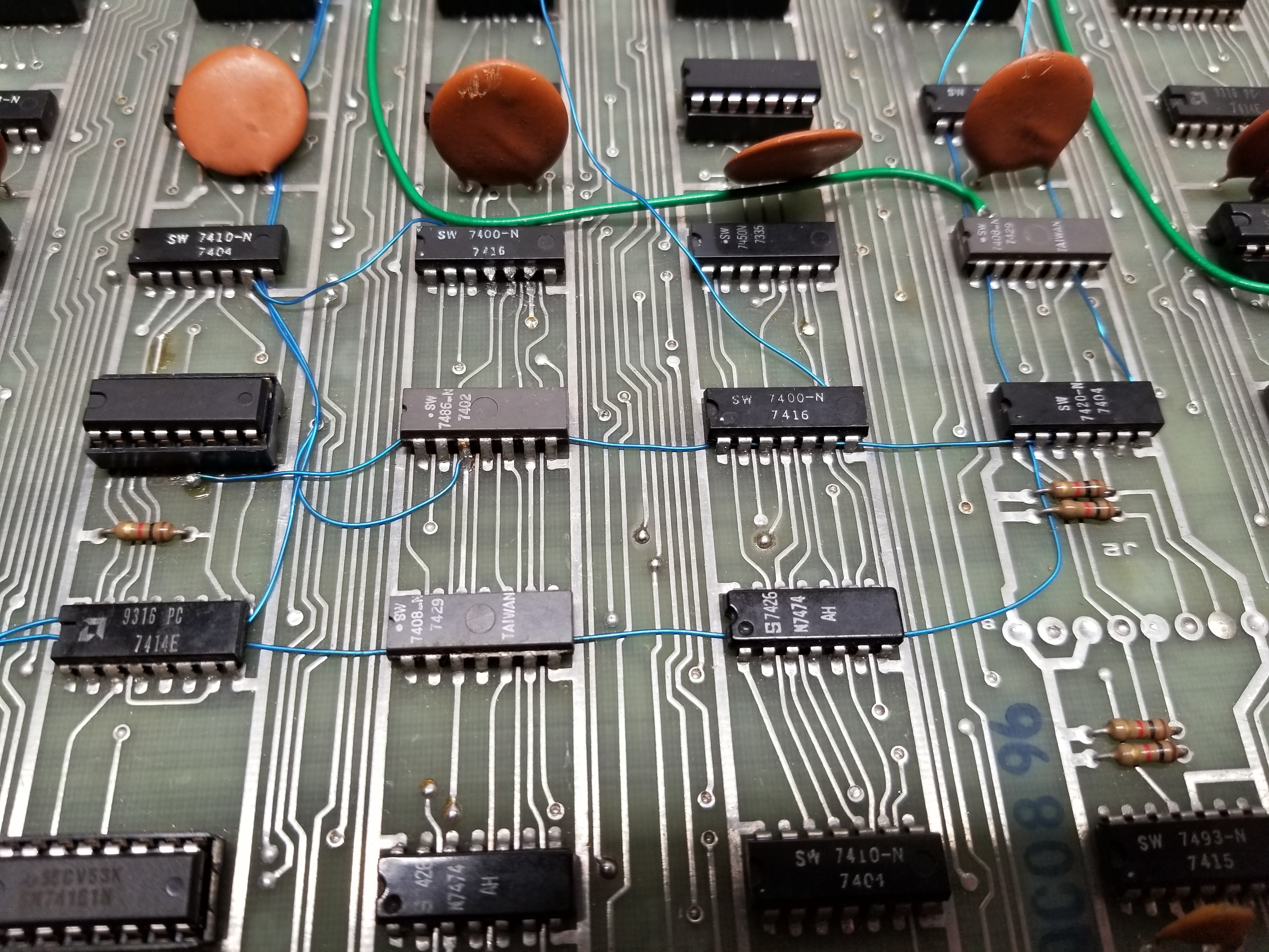
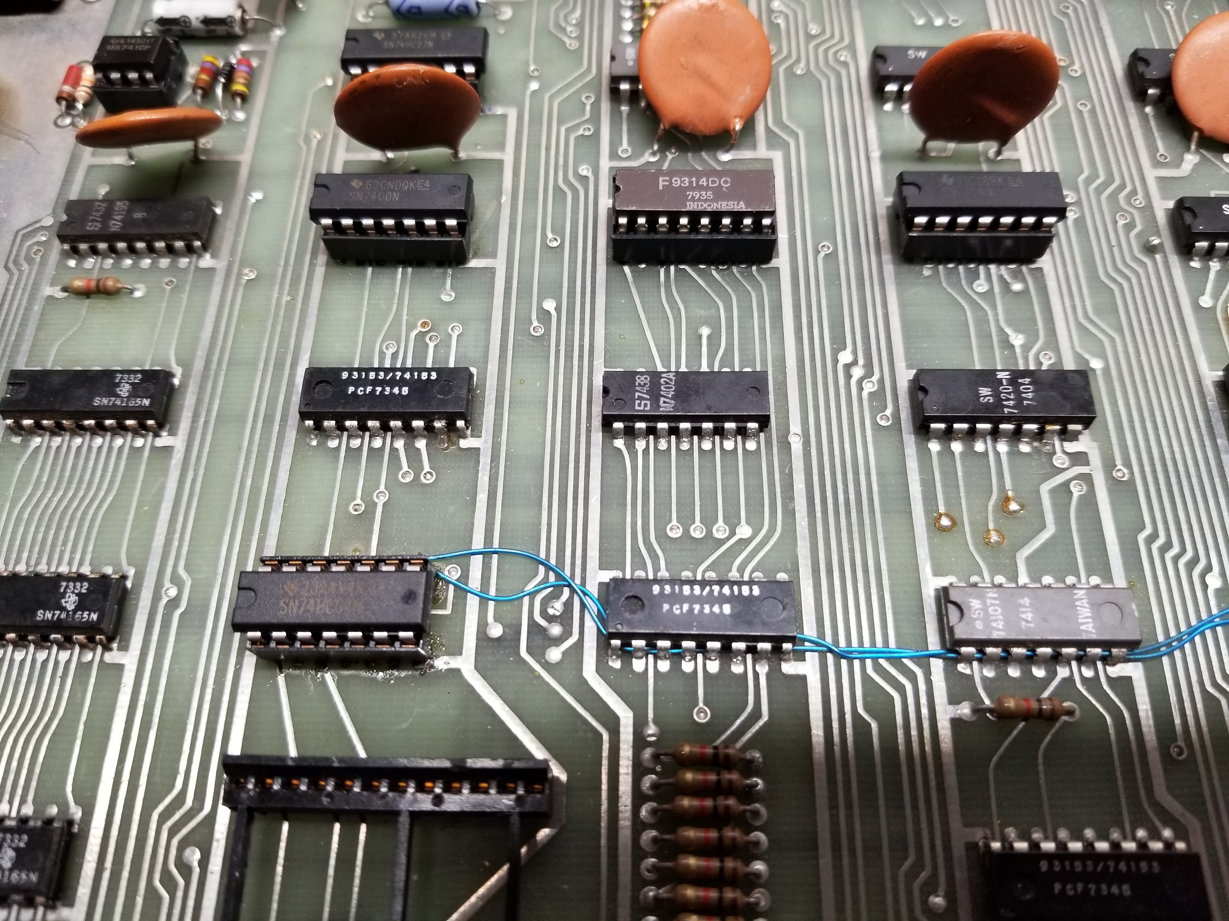
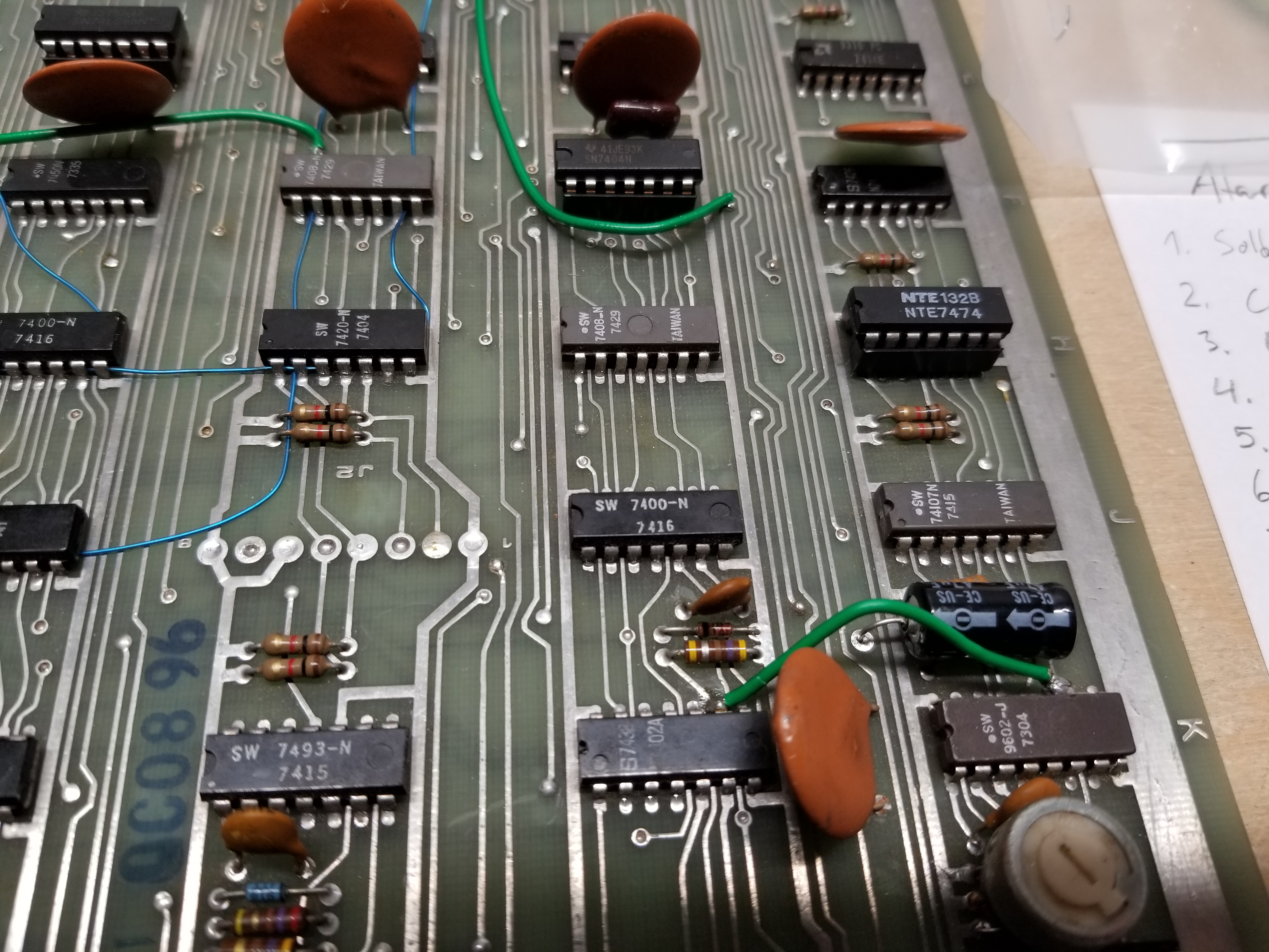
Factory Modifications Made on the Revision-C PCB
I compiled this list since I found myself in a position where I desperately needed this information. :)
SCV games also has high-res closeups of another REV-C board that is in better condition than mine. (1/5/2022: Link removed; page no longer exists.)
This list probably isn't complete, but I hope it helps in lieu of a REV-C manual!
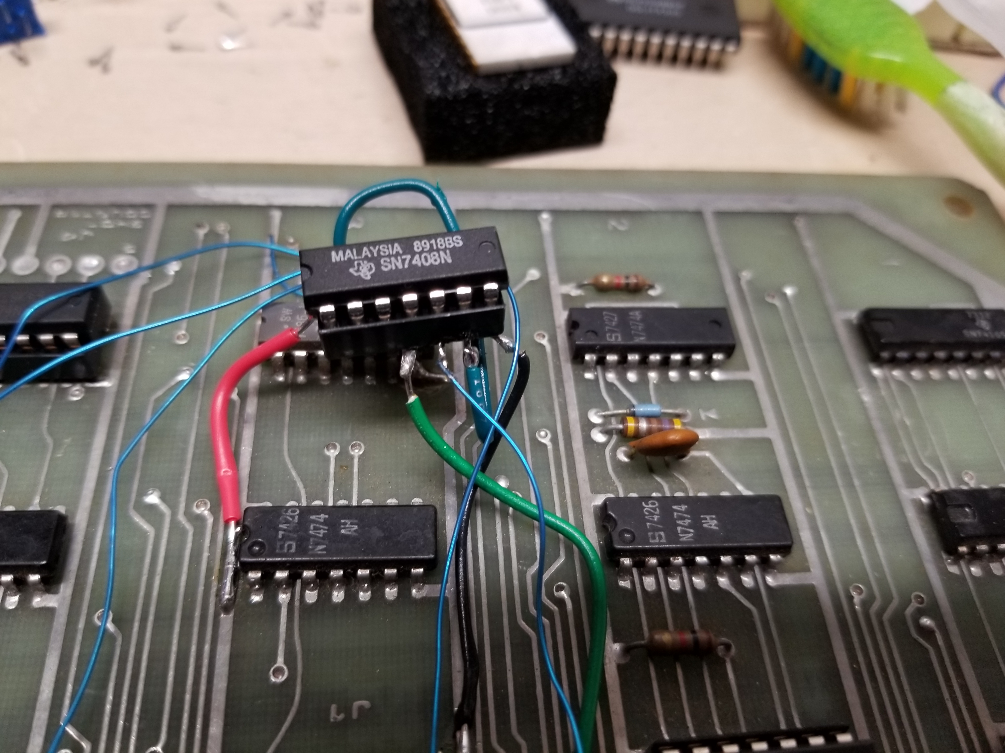
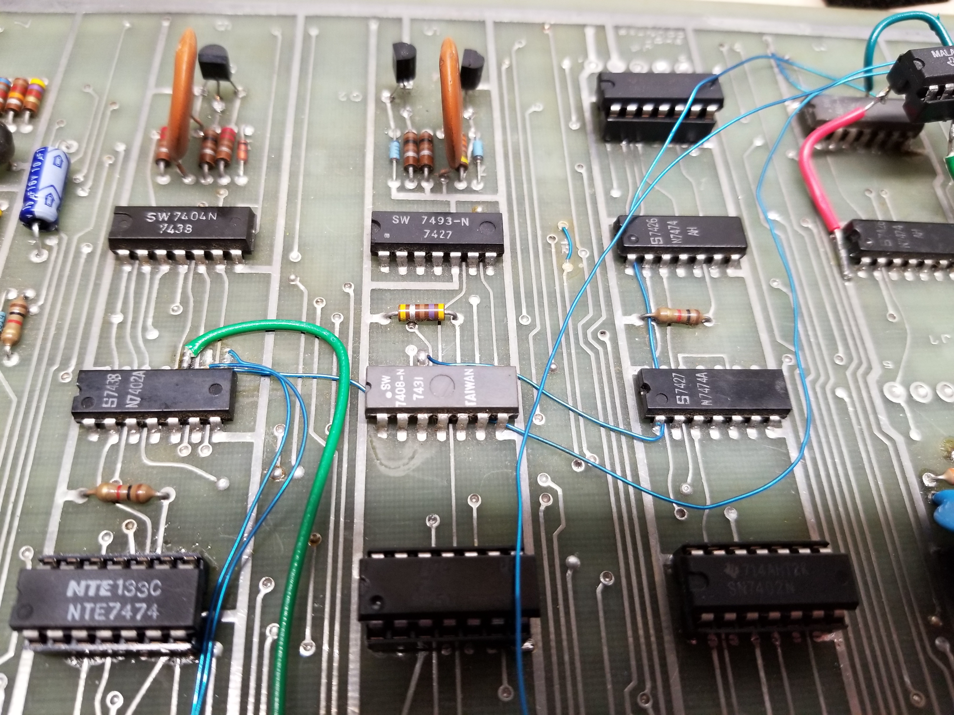
- Piggyback a 7408 on top of A3 with all pins splayed out. Bend down pin 14 and pin 7 and solder it to A3. The rest of the pins should be bent horizontal.
- Connect pin 10 of A3 to pin 6 of the piggybacked chip.
- Connect pin 9, A3 to the VCC/+5V rail.
- Cut and lift pin 12 of the 7408 at C5 and connect it to pin 8 of the bottom chip at A3.
- Connect pin 8 of J9 to pin 5 of the piggybacked chip at A3.
- Connect pin 6 of F2 to pin 4 of the piggybacked chip at A3.
- Connect pin 9 of the piggybacked chip at A3 to pin 9 of H4.
- Connect pin 10 of the piggybacked chip at A3 to pin 8 of C6.
- Connect pin 8 of the piggybacked chip at A3 to pin 5 of H6.
- Connect pin 9 of C6 to pin 3 of H5.
- Connect pin 10 of C6 to pin 13 of F3.
- Cut and lift pins 4-6 of F5. Do not connect them to anything.
- Connect pin 6 of F6 to pin 13 of F5.
- Connect pin 9 of K2 to pin 11 of K1.
- Cut the trace between pins 5 and 8 of H6 on the solder side of the board.
- Cut the trace leading to pin 15 of H6 on the solder side of the board.
- Cut the trace coming from pin 13 of the card edge connector on the solder side of the board, and solder an A14F diode over the gap with the banded side facing away from the edge connector. Make sure it does not touch that capacitor pad that is right next to it.
Modification pictures:
Misc. Images
Misc. Info
If your light gun is missing the lens, do not fret. I have been able to adjust mine so that it works without the lens. You will need to hold it closer to the screen, though.
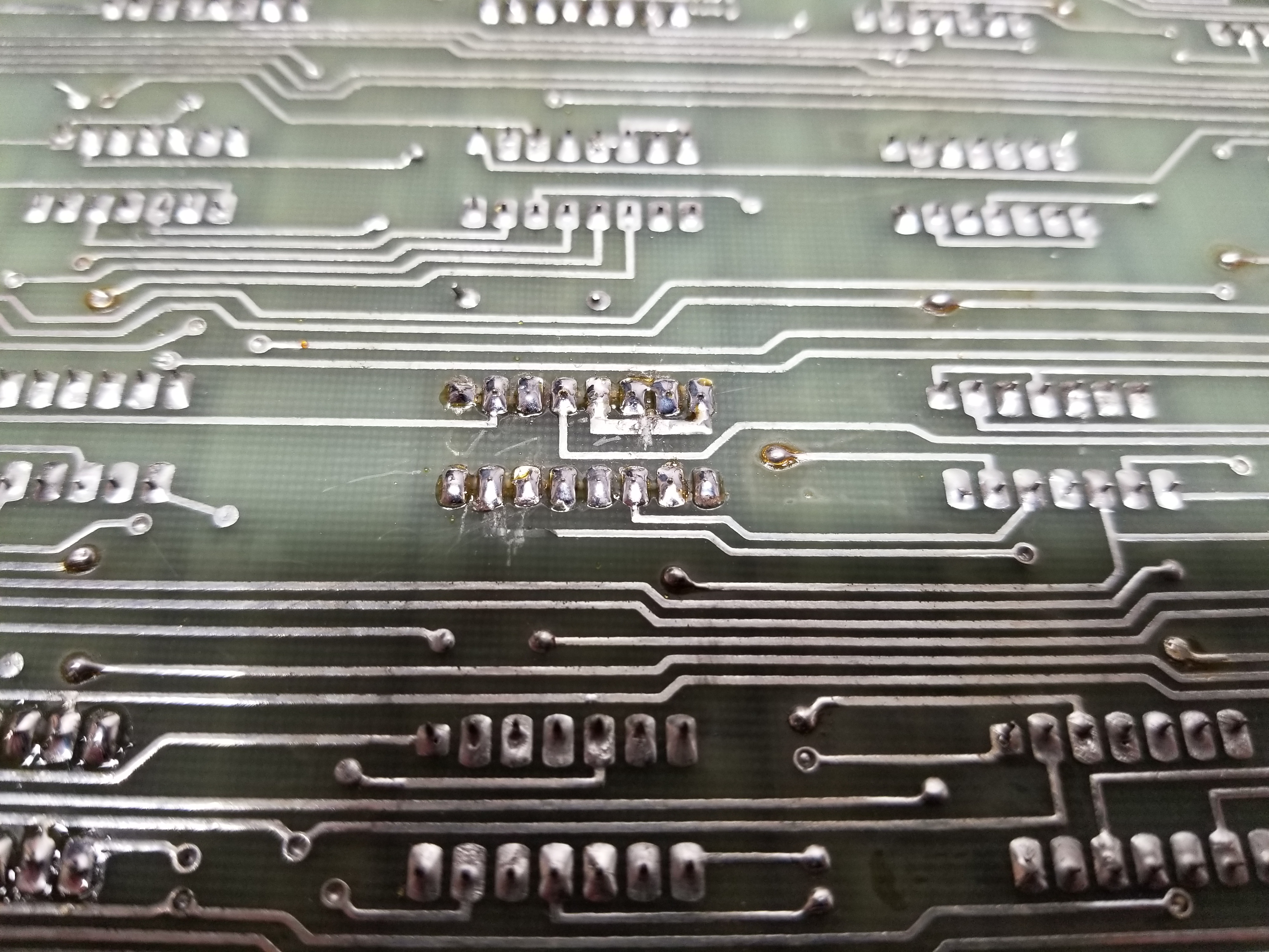
The traces on QWAK! are just trash. On the topside of the board, pads for logic chips are very thin to allow traces to run between the pins on the chips. Unfortunately, the draftsman made them so thin that there is almost no trace surrounding the via. This is why they break and come off so easily. For the sake of your board, please be sure to socket every chip that you replace!
There is a slight difference between the dies of the LM311V and LM311N when compared to the LM311P. In some designs, the N variant cannot be replaced with the P variant. Some engineers at Texas Instruments noted this.
When I was fixing the light gun, I found a cool signal so I took a video. This is the output of pin 3 of the 74107 at L1. This shows how the circuit determines the exact pixel that the gun is pointing at. (I recorded the video moving the gun up and down because the signal difference is much more noticable than a left or right movement.)
When looking at various pictures of Atari light gun optics boards on the internet, I noticed that several of them had different values for R8. (The lone resistor on the left side of the LM311.) I asked Ed if he knew if they corresponded to different PCB revisions. He said he didn't. He also sent me a schematic where an OP had detailed a couple of mods they made on the light gun board. They said that changing R8 to 330 ohms increased the sensitivity of the light gun. I tried it, and found no noticible difference in performance or the output signal on my scope. Since I had also seen 680 and 1K ohms for R8, I tried those too. No change.
I also saw a light gun board that had a 6.5K ohm resistor instead of the standard 680/1K at R8. It also had the LM311P. I was unable to get my board to work with those changes. They must have also changed one of the values of the capacitors to accomodate the die difference.
This page was probably published sometime in September 2018.
This page was last updated 1/5/2022
Spelling, grammar, and readability corrections.